TP-Link T1500G-10PS T1500G-10PSUN V1 User Guide - Page 96
Application Example for STP Function
 |
View all TP-Link T1500G-10PS manuals
Add to My Manuals
Save this manual to your list of manuals |
Page 96 highlights
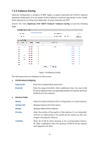
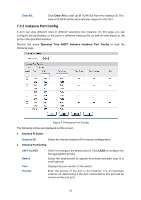
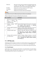
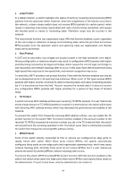
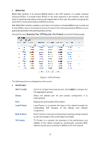
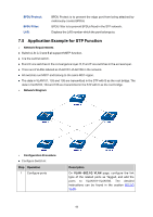
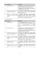
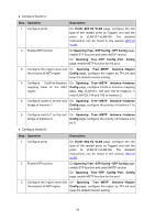
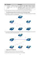
BPDU Protect: BPDU Filter: LAG: BPDU Protect is to prevent the edge port from being attacked by maliciously created BPDUs BPDU Filter is to prevent BPDUs flood in the STP network. Displays the LAG number which the port belongs to. 7.5 Application Example for STP Function Network Requirements Switch A, B, C, D and E all support MSTP function. A is the central switch. B and C are switches in the convergence layer. D, E and F are switches in the access layer. There are 6 VLANs labeled as VLAN101-VLAN106 in the network. All switches run MSTP and belong to the same MST region. The data in VLAN101, 103 and 105 are transmitted in the STP with B as the root bridge. The data in VLAN102, 104 and 106 are transmitted in the STP with C as the root bridge. Network Diagram Configuration Procedure Configure Switch A: Step Operation 1 Configure ports Description On VLAN→802.1Q VLAN page, configure the link type of the related ports as Tagged, and add the ports to VLAN101-VLAN106. The detailed instructions can be found in the section 802.1Q VLAN. 86
-
 1
1 -
2
-
3
-
4
-
5
-
6
-
7
-
8
-
9
-
10
-
11
-
12
-
13
-
14
-
15
-
16
-
17
-
18
-
19
-
20
-
21
-
22
-
23
-
24
-
25
-
26
-
27
-
28
-
29
-
30
-
31
-
32
-
33
-
34
-
35
-
36
-
37
-
38
-
39
-
40
-
41
-
42
-
43
-
44
-
45
-
46
-
47
-
48
-
49
-
50
-
51
-
52
-
53
-
54
-
55
-
56
-
57
-
58
-
59
-
60
-
61
-
62
-
63
-
64
-
65
-
66
-
67
-
68
-
69
-
70
-
71
-
72
-
73
-
74
-
75
-
76
-
77
-
78
-
79
-
80
-
81
-
82
-
83
-
84
-
85
-
86
-
87
-
88
-
89
-
90
-
 91
91 -
 92
92 -
 93
93 -
 94
94 -
 95
95 -
 96
96 -
 97
97 -
 98
98 -
 99
99 -
 100
100 -
 101
101 -
102
-
103
-
104
-
105
-
106
-
107
-
108
-
109
-
110
-
111
-
112
-
113
-
114
-
115
-
116
-
117
-
118
-
119
-
120
-
121
-
122
-
123
-
124
-
125
-
126
-
127
-
128
-
129
-
130
-
131
-
132
-
133
-
134
-
135
-
136
-
137
-
138
-
139
-
140
-
141
-
142
-
143
-
144
-
145
-
146
-
147
-
148
-
149
-
150
-
151
-
152
-
153
-
154
-
155
-
156
-
157
-
158
-
159
-
160
-
161
-
162
-
163
-
164
-
165
-
166
-
167
-
168
-
169
-
170
-
171
-
172
-
173
-
174
-
175
-
176
-
177
-
178
-
179
-
180
-
181
-
182
-
183
-
184
-
185
-
186
-
187
-
188
-
189
-
190
-
191
-
192
-
193
-
194
-
195
-
196
-
197
-
198
-
199
-
200
-
201
-
202
-
203
-
204
-
205
-
206
-
207
-
208
-
209
-
210
-
211
-
212
-
213
-
214
-
215
-
216
-
217
-
218
-
219
-
220
-
221
-
222
-
223
-
224
-
225
-
226
-
227
-
228
-
229
-
230
-
231
-
232
-
233
-
234
-
235
-
236
-
237
-
238
-
239
-
240
-
241
-
242
 |
 |
