TP-Link T2500-28TCTL-SL5428E T2500-28TCUN V1 Installation Guide
TP-Link T2500-28TCTL-SL5428E Manual
 |
View all TP-Link T2500-28TCTL-SL5428E manuals
Add to My Manuals
Save this manual to your list of manuals |
TP-Link T2500-28TCTL-SL5428E manual content summary:
- TP-Link T2500-28TCTL-SL5428E | T2500-28TCUN V1 Installation Guide - Page 1
Business Networking Solution Installation Guide L2 Managed Switch T2500-28TC (TL-SL5428E) - TP-Link T2500-28TCTL-SL5428E | T2500-28TCUN V1 Installation Guide - Page 2
. This equipment generates, uses, and can radiate radio frequency energy and, if not installed and used in accordance with the instruction manual, may cause harmful interference to radio communications. Operation of this equipment in a residential area is likely to cause harmful interference - TP-Link T2500-28TCTL-SL5428E | T2500-28TCUN V1 Installation Guide - Page 3
http://www.tp-link.com About this Installation Guide This Installation Guide describes the hardware characteristics, installation methods and the Configuration. This chapter instructs you to configure the switch via Web Interface and CLI commands. Appendix A Troubleshooting. Appendix B Hardware - TP-Link T2500-28TCTL-SL5428E | T2500-28TCUN V1 Installation Guide - Page 4
the specific formats to highlight special messages. The following table lists the notice icons that are used throughout this guide. Remind to be careful. A caution indicates a potential which may result in device damage. Remind to take notice. The note contains the helpful information for a better - TP-Link T2500-28TCTL-SL5428E | T2500-28TCUN V1 Installation Guide - Page 5
13 4.4 Verify Installation 14 4.5 Power On 14 4.6 Initialization 15 Chapter 5 Configuration 16 5.1 Configure the Switch via GUI 16 5.2 Configure the Switch Using CLI 17 Appendix A Troubleshooting----------- 21 Appendix B Hardware Specifications------- 22 Contents IV - TP-Link T2500-28TCTL-SL5428E | T2500-28TCUN V1 Installation Guide - Page 6
, designed for workgroups and departments, provides wire-speed performance and abundant layer 2 management features. It provides a variety of service features and multiple powerful functions with high security. The EIA-standardized framework and smart configuration capacity can provide flexible - TP-Link T2500-28TCTL-SL5428E | T2500-28TCUN V1 Installation Guide - Page 7
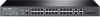
L2 Managed Switch Note: The port 25-28 of the switch are "Combo" ports. A "Combo" port consists of a RJ45 port and an SFP port, and the two ports share the same LED. Port Feature Model T2500-28TC Console Port 1 10/100Mbps RJ45 Port 24 10/100/1000Mbps RJ45 Port 4 SFP Port 4 Console Port - TP-Link T2500-28TCTL-SL5428E | T2500-28TCUN V1 Installation Guide - Page 8
L2 Managed Switch Power Socket Connect the female connector of the power cord here, and the male connector to the AC power outlet. Please make sure the voltage of the power supply meets the requirement of the input voltage (100-240V~ 50/60Hz). Caution: Please use the provided power cord. 03 - TP-Link T2500-28TCTL-SL5428E | T2500-28TCUN V1 Installation Guide - Page 9
contact your distributor. One Switch One Power Cord and one This Installation Guide Console Cable T2500-28TC (TL-SL5428E) One Resource CD Two mounting cleaning method. ■■ Site Requirements To ensure normal operation and long service life of the device, please install it in an environment that - TP-Link T2500-28TCTL-SL5428E | T2500-28TCUN V1 Installation Guide - Page 10
, mechanical property changes and corrosions. Too high temperature may accelerate aging of the insulation materials and can thus significantly shorten the service life of the device. For normal temperature and humidity of the device, please check the following table. Environment Operating Storage - TP-Link T2500-28TCTL-SL5428E | T2500-28TCUN V1 Installation Guide - Page 11
the device on a rack or a flat workbench, please note the following items: ■■ The rack or workbench is flat and stable, and sturdy enough to support the weight of 5.5kg at least. ■■ The rack or workbench has a good ventilation system. The equipment room is well ventilated. ■■ The rack is well - TP-Link T2500-28TCTL-SL5428E | T2500-28TCUN V1 Installation Guide - Page 12
of the Device Notch Figure 2-1 Desktop Installation ■■ Rack Installation To install the device in an EIA standard-sized, 19-inch rack, follow the instructions described below: 1. Check the grounding and stability of the rack. 2. Secure the supplied rack-mounting brackets to each side of the device - TP-Link T2500-28TCTL-SL5428E | T2500-28TCUN V1 Installation Guide - Page 13
L2 Managed Switch Chapter 3 Lightning Protection 3.1 Cabling Reasonably In the actual network environment, you may need cable outdoors and indoors, and the requirements for cabling outdoors and indoors are different. A reasonable cabling system can decrease the damage of induced lightning to devices - TP-Link T2500-28TCTL-SL5428E | T2500-28TCUN V1 Installation Guide - Page 14
table. Ethernet Cable Other Pipelines Min Parallel Net Length Min Parallel-overlapping Net Height L (mm) H (mm) Down-conductor 1000 300 PE 50 20 Service pipe 150 20 Compressed air pipe 150 20 Thermal pipe (not wrapped) 500 500 Thermal pipe (wrapped) 300 300 Gas pipe 300 20 - TP-Link T2500-28TCTL-SL5428E | T2500-28TCUN V1 Installation Guide - Page 15
, which is also a necessary measure to protect the body from electric shock. In different environments, the device may be grounded differently. The following will instruct you to connect the device to the ground in two ways, connecting to the grounding bar or connecting to the ground via the power - TP-Link T2500-28TCTL-SL5428E | T2500-28TCUN V1 Installation Guide - Page 16
L2 Managed Switch Note: ■■ The figure is to illustrate the application and principle. The power cord you get from the package and the socket in your situation will comply with the regulation in your country, so they may differ from the figure above. ■■ If you intend to connect the device to the - TP-Link T2500-28TCTL-SL5428E | T2500-28TCUN V1 Installation Guide - Page 17
L2 Managed Switch 3.4 Use Lightning Arrester Power lightning arrester and signal lightning arrester are used for lighting protection. Power lightning arrester is used for limiting the voltage surge due to a lightning. If an outdoor AC power cord should be directly connected to the device, please use - TP-Link T2500-28TCTL-SL5428E | T2500-28TCUN V1 Installation Guide - Page 18
L2 Managed Switch Chapter 4 Connection 4.1 Ethernet Port Connect the Ethernet ports of the switch to the network devices by RJ45 cable as the following figure shows. RJ45 Port RJ45 Cable Figure 4-1 Connecting the RJ45 Port 4.2 SFP Port Connect the SFP port to an SFP module. For the switch, if an - TP-Link T2500-28TCTL-SL5428E | T2500-28TCUN V1 Installation Guide - Page 19
Managed Switch Figure 4-3 Connecting the Console Port You can also manage the device through the console port, for details please refer to the CLI Reference Guide on the resource CD. Note: ■■ The console port is the first port on the left of the front panel. ■■ Please keep the device power off - TP-Link T2500-28TCTL-SL5428E | T2500-28TCUN V1 Installation Guide - Page 20
L2 Managed Switch Note: The figure is to illustrate the application and principle. The power cord you get from the package and the socket in your situation will comply with the regulation in your country, so they may differ from the figure above. 4.6 Initialization After the device is powered on, it - TP-Link T2500-28TCTL-SL5428E | T2500-28TCUN V1 Installation Guide - Page 21
L2 Managed Switch Chapter 5 Configuration 5.1 Configure the Switch via GUI Note: To log on to the GUI of the switch, the IP address of your PC should be set in the same subnet addresses of the switch. The IP address is 192.168.0.x ("x" is any number from 2 to 254), Subnet Mask is 255.255.255.0. 1. - TP-Link T2500-28TCTL-SL5428E | T2500-28TCUN V1 Installation Guide - Page 22
L2 Managed Switch 5.2 Configure the Switch Using CLI You can log on to the switch and access the CLI by the following two methods: ■■ Log on to the switch by the console port on the switch. ■■ Log on to the switch remotely by a Telnet or SSH connection through an Ethernet port. ■■ Logon by a Console - TP-Link T2500-28TCTL-SL5428E | T2500-28TCUN V1 Installation Guide - Page 23
4. Select the port to connect in Figure 5-6, and click OK. L2 Managed Switch Figure 5-6 Select the port to connect 5. Configure the port selected in the step above as the following Figure 5-7 shows. Configure Bits per second as 38400, Data bits as 8, Parity as None, Stop bits as 1, Flow control as - TP-Link T2500-28TCTL-SL5428E | T2500-28TCUN V1 Installation Guide - Page 24
login mode, login authentication information and Privileged EXEC Mode password should be configured through Console connection. For more details please refer to the CLI Reference Guide on the resource CD. Here we take login local mode as an example. 2. Make sure the switch and the PC are in the same - TP-Link T2500-28TCTL-SL5428E | T2500-28TCUN V1 Installation Guide - Page 25
Enter button, then you can use the CLI now, which is shown as Figure 5-12. Figure 5-12 Log in the Switch For detailed CLI configuration instructions, please refer to the CLI Reference Guide on the resource CD. Configuration 20 - TP-Link T2500-28TCTL-SL5428E | T2500-28TCUN V1 Installation Guide - Page 26
L2 Managed Switch Appendix A Troubleshooting Q1. What could I do if I forgot the username and password of the switch? 1. Connect the console port of the PC to the correct: configure Bits per second as 38400, Data bits as 8, Parity as None, Stop bits as 1, and Flow control as None. 21 Troubleshooting - TP-Link T2500-28TCTL-SL5428E | T2500-28TCUN V1 Installation Guide - Page 27
℃ Operating Humidity 10%~90%RH Non-condensing Storage Humidity 5%~90%RH Non-condensing ■■ For more help, please go to: http://www.tp-link.com/en/support/faq ■■ To download the latest Firmware, Driver, Utility and User Guide, go to: http://www.tp-link.com/en - TP-Link T2500-28TCTL-SL5428E | T2500-28TCUN V1 Installation Guide - Page 28
Website: http://www.tp-link.com Tel: +86 755 26504400 E-mail: [email protected] 7106506261 REV1.1.0
-
 1
1 -
 2
2 -
 3
3 -
 4
4 -
 5
5 -
 6
6 -
 7
7 -
8
-
9
-
10
-
11
-
12
-
13
-
14
-
15
-
16
-
17
-
18
-
19
-
20
-
21
-
22
-
23
-
24
-
25
-
26
-
27
-
28
 |
 |

Installation Guide
L2 Managed Switch
T2500-28TC (TL-SL5428E)
Business Networking Solution