TP-Link T2500-28TCTL-SL5428E T2500-28TCUN V1 Installation Guide - Page 18
Connection
 |
View all TP-Link T2500-28TCTL-SL5428E manuals
Add to My Manuals
Save this manual to your list of manuals |
Page 18 highlights
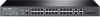
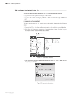
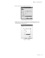
L2 Managed Switch Chapter 4 Connection 4.1 Ethernet Port Connect the Ethernet ports of the switch to the network devices by RJ45 cable as the following figure shows. RJ45 Port RJ45 Cable Figure 4-1 Connecting the RJ45 Port 4.2 SFP Port Connect the SFP port to an SFP module. For the switch, if an SFP transceiver (purchased separately) is installed in a slot and has a valid link on the port, the associated RJ45 port will be disabled and cannot be used. SFP Port SFP Module Figure 4-2 Inserting the SFP Module 4.3 Console Port CLI (Command Line Interface) enables you to manage the switch, thus you can load the CLI after connecting the PCs or Terminals to the console port on the switch via the provided cable. Connect the console port of the device with your computer by the console cable as the following figure shows. 13 Connection
-
 1
1 -
2
-
3
-
4
-
5
-
6
-
7
-
8
-
9
-
10
-
11
-
12
-
 13
13 -
 14
14 -
 15
15 -
 16
16 -
 17
17 -
 18
18 -
 19
19 -
 20
20 -
 21
21 -
 22
22 -
 23
23 -
24
-
25
-
26
-
27
-
28
 |
 |
