TP-Link T2500-28TCTL-SL5428E T2500-28TCUN V1 Installation Guide - Page 7
Rear Panel
 |
View all TP-Link T2500-28TCTL-SL5428E manuals
Add to My Manuals
Save this manual to your list of manuals |
Page 7 highlights
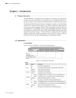
L2 Managed Switch Note: The port 25-28 of the switch are "Combo" ports. A "Combo" port consists of a RJ45 port and an SFP port, and the two ports share the same LED. Port Feature Model T2500-28TC Console Port 1 10/100Mbps RJ45 Port 24 10/100/1000Mbps RJ45 Port 4 SFP Port 4 Console Port Designed to connect with the serial port of a computer or terminal for monitoring and configuring the switch. 10/100Mbps Port Designed to connect to the device with a bandwidth of 10Mbps or 100Mbps. Each has a corresponding 10/100M LED. 10/100/1000Mbps Port Designed to connect to the device with a bandwidth of 10Mbps, 100Mbps or 1000Mbps. Each has a corresponding 1000M LED. SFP Port Designed to install the SFP module. The switch features some SFP transceiver slots that are shared with the associated RJ45 ports. The associated two ports are referred as a "Combo" port, which means they cannot be used simultaneously, otherwise only SFP port works. ■■ Rear Panel The rear panel of T2500-28TC is shown as the following figure. Grounding Terminal Power Socket Figure 1-2 Rear Panel of T2500-28TC Grounding Terminal The switch already comes with lightning protection mechanism. You can also ground the switch through the PE (Protecting Earth) cable of AC cord or with Ground Cable. For detailed information, please refer to Chapter 3 Lightning Protection. Introduction 02
-
 1
1 -
 2
2 -
 3
3 -
 4
4 -
 5
5 -
 6
6 -
 7
7 -
 8
8 -
 9
9 -
 10
10 -
 11
11 -
 12
12 -
13
-
14
-
15
-
16
-
17
-
18
-
19
-
20
-
21
-
22
-
23
-
24
-
25
-
26
-
27
-
28
 |
 |
