TP-Link TL-SG2424P TL-SG2424P V1 IG 7106504146 - Page 23
Verify Installation, Power On, ´1´, Initialization
 |
View all TP-Link TL-SG2424P manuals
Add to My Manuals
Save this manual to your list of manuals |
Page 23 highlights
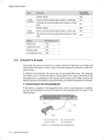
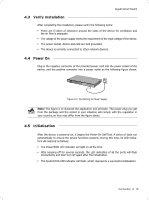
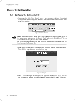
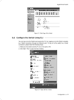
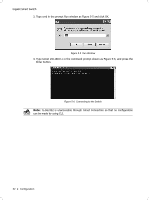
Gigabit Smart Switch 4444 Verify Installation After completing the installation, please verify the following items: ■■ There are 5~10cm of clearance around the sides of the device for ventilation and the air flow is adequate. ■■ The voltage of the power supply meets the requirement of the input voltage of the device. ■■ The power socket, device and rack are well grounded. ■■ The device is correctly connected to other network devices. 4444 Power On Plug in the negative connector of the provided power cord into the power socket of the device, and the positive connector into a power outlet as the following figure shown. FFFFFFFFFFFFConnecting to Power Supply Note: The figure is to illustrate the application and principle. The power plug you get from the package and the socket in your situation will comply with the regulation in your country, so they may differ from the figure above. 4444 Initialization After the device is powered on, it begins the Power-On Self-Test. A series of tests run automatically to ensure the device functions properly. During this time, its LED indicators will respond as follows: ■■ The Power/PWR LED indicator will light on all the time. ■■ After keeping off for several seconds, the LED indicators of all the ports will flash momentarily and then turn off again after the initialization. ■■ The System/SYS LED indicator will flash, which represents a successful initialization. Connection 19
-
 1
1 -
2
-
3
-
4
-
5
-
6
-
7
-
8
-
9
-
10
-
11
-
12
-
13
-
14
-
15
-
16
-
17
-
 18
18 -
 19
19 -
 20
20 -
 21
21 -
 22
22 -
 23
23 -
 24
24 -
 25
25 -
 26
26 -
 27
27 -
 28
28 -
29
-
30
-
31
-
32
 |
 |