TP-Link TL-SG2424P TL-SG2424P V1 IG 7106504146 - Page 8
LED Mode Switch Button, Reset, 100/1000Mbps RJ45 Port, SFP Port - 24
 |
View all TP-Link TL-SG2424P manuals
Add to My Manuals
Save this manual to your list of manuals |
Page 8 highlights
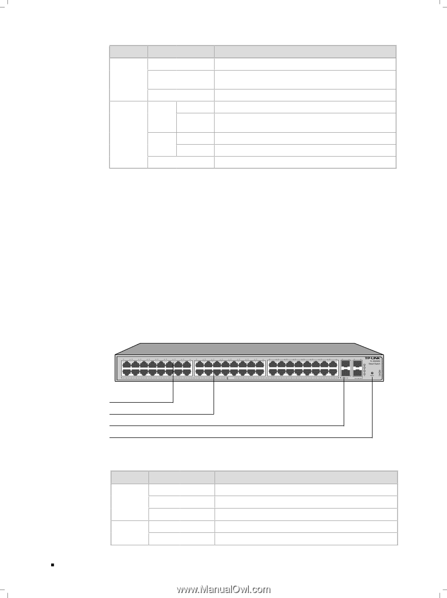
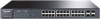
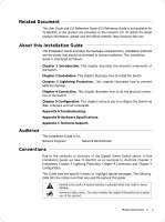
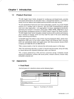
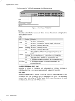
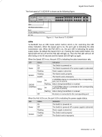
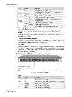
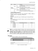
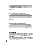
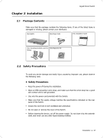
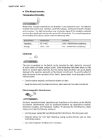
Gigabit Smart Switch LED Status On PoE Max Flashing Off 10/100/ 1000Mbps Green Yellow Off On Flashing On Flashing Indication The remaining PoE power≤7W The remaining PoE power keeps ≤7W after this LED is on for 2 minutes The remaining PoE power≥7W The port is supplying power normally The supply power exceeds the correponding port's maximum power Overload or short circuit is detected Power-on self-test has failed No PoE power supply is provided on the port LED Mode Switch Button Press this button to switch the LED status indication between Speed and PoE. Reset Press this button for five seconds or above to reset the software setting back to factory default settings. 10/100/1000Mbps RJ45 Port Designed to connect to the device with a bandwidth of 10Mbps, 100Mbps or 1000Mbps. Each has a corresponding 1000Mbps LED. SFP Port Designed to install the SFP module. TL-SG2424P Switch features 4 SFP transceiver 52 slots that are shared with the associated RJ45 ports. The associated two ports are 5 50 49 1 23 45 67 89 10 11 12 13 14 15 16 17 18 19 20 21 22 23 24 25 26 27 28 29 30 31 32 33 34 35 36 37 38 39 40 41 42 43 44 45 46 47 48 49 50 51 52 referred as a "Combo" port, which means they cannot be used simultaneously, otherwise only SFP port works. 100Mbps 10Mbps 1000Mbps 10/100Mbps 1000Base-X The front panel of TL-SG2452 is shown as the following figure. 1 23 45 67 89 10 11 12 13 14 15 16 17 18 19 20 21 22 23 24 25 26 27 28 29 30 31 32 33 34 35 36 37 38 39 40 41 42 43 44 45 46 47 48 49 50 51 52 1000Mbps 10/100Mbps 1000Base-X LEDs 10/100/1000Mbps RJ45 Port 1000Base-X SFP Port 1000Mbps 10/100Mbps Reset FFFFFFFFFFF Front Panel of TL-SG2452 LEDs LED PWR SYS Status On Off Flashing Flashing On/Off Indication The Switch is powered on The Switch is powered off or power supply is abnormal Power supply is abnormal The Switch works properly The Switch works improperly 04 Introduction
-
 1
1 -
2
-
 3
3 -
 4
4 -
 5
5 -
 6
6 -
 7
7 -
 8
8 -
 9
9 -
 10
10 -
 11
11 -
 12
12 -
 13
13 -
14
-
15
-
16
-
17
-
18
-
19
-
20
-
21
-
22
-
23
-
24
-
25
-
26
-
27
-
28
-
29
-
30
-
31
-
32
 |
 |