TP-Link TL-SG5412F TL-SG5412F V1 User Guide - Page 18
Rear Panel
 |
View all TP-Link TL-SG5412F manuals
Add to My Manuals
Save this manual to your list of manuals |
Page 18 highlights
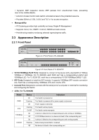
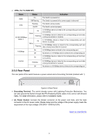
LEDs ( for TL-SG5412F) Name Status Indication PWR On Off/Flashing The Switch is powered on The Switch is powered off or power supply is abnormal SYS Flashing On/Off The Switch works properly The Switch works improperly 10/100/1000Mbps BASE-T Green Yellow On A 1000Mbps device is linked to the corresponding port and there is no activity Flashing A 1000Mbps device is linked to the corresponding port and data is being transmitted or received On A 10/100Mbps device is linked to the corresponding port and there is no activity Flashing A 10/100Mbps device is linked to the corresponding port and data is being transmitted or received 1000Mbps On A 1000Mbps device is linked to the corresponding port Off No device or a 10/100Mbps device is linked to the corresponding port On A 1000Mbps device is linked to the corresponding port but there is no activity Link/Act Flashing A 1000Mbps device is linked to the corresponding port and data is being transmitted or received Off No device or a 10/100Mbps device is linked to the corresponding port 2.3.2 Rear Panel The rear panel of the switch features a power socket and a Grounding Terminal (marked with ). Figure 2-3 Rear Panel Grounding Terminal: The switch already comes with Lightning Protection Mechanism. You can also ground the Switch through the PE (Protecting Earth) cable of AC cord or with Ground Cable. For detail information, please refer to Installation Guide. AC Power Socket: Connect the female connector of the power cord here, and the male connector to the AC power outlet. Please make sure the voltage of the power supply meets the requirement of the input voltage (100-240V~ 50/60Hz 0.6A). Return to CONTENTS 9
-
 1
1 -
2
-
3
-
4
-
5
-
6
-
7
-
8
-
9
-
10
-
11
-
12
-
 13
13 -
 14
14 -
 15
15 -
 16
16 -
 17
17 -
 18
18 -
 19
19 -
 20
20 -
 21
21 -
 22
22 -
 23
23 -
24
-
25
-
26
-
27
-
28
-
29
-
30
-
31
-
32
-
33
-
34
-
35
-
36
-
37
-
38
-
39
-
40
-
41
-
42
-
43
-
44
-
45
-
46
-
47
-
48
-
49
-
50
-
51
-
52
-
53
-
54
-
55
-
56
-
57
-
58
-
59
-
60
-
61
-
62
-
63
-
64
-
65
-
66
-
67
-
68
-
69
-
70
-
71
-
72
-
73
-
74
-
75
-
76
-
77
-
78
-
79
-
80
-
81
-
82
-
83
-
84
-
85
-
86
-
87
-
88
-
89
-
90
-
91
-
92
-
93
-
94
-
95
-
96
-
97
-
98
-
99
-
100
-
101
-
102
-
103
-
104
-
105
-
106
-
107
-
108
-
109
-
110
-
111
-
112
-
113
-
114
-
115
-
116
-
117
-
118
-
119
-
120
-
121
-
122
-
123
-
124
-
125
-
126
-
127
-
128
-
129
-
130
-
131
-
132
-
133
-
134
-
135
-
136
-
137
-
138
-
139
-
140
-
141
-
142
-
143
-
144
-
145
-
146
-
147
-
148
-
149
-
150
-
151
-
152
-
153
-
154
-
155
-
156
-
157
-
158
-
159
-
160
-
161
-
162
-
163
-
164
-
165
-
166
-
167
-
168
-
169
-
170
-
171
-
172
-
173
-
174
-
175
-
176
-
177
-
178
-
179
-
180
-
181
-
182
-
183
-
184
-
185
-
186
-
187
-
188
-
189
-
190
-
191
-
192
-
193
-
194
-
195
-
196
-
197
-
198
-
199
-
200
-
201
-
202
-
203
-
204
-
205
-
206
-
207
-
208
-
209
-
210
-
211
-
212
-
213
-
214
-
215
-
216
-
217
-
218
-
219
-
220
-
221
-
222
-
223
-
224
-
225
-
226
-
227
-
228
-
229
-
230
-
231
-
232
-
233
-
234
-
235
-
236
-
237
-
238
-
239
-
240
-
241
-
242
-
243
-
244
-
245
-
246
-
247
-
248
-
249
-
250
-
251
-
252
-
253
-
254
-
255
-
256
-
257
 |
 |
