TP-Link TL-SG5412F TL-SG5412F V1 User Guide - Page 82
Pvlan
 |
View all TP-Link TL-SG5412F manuals
Add to My Manuals
Save this manual to your list of manuals |
Page 82 highlights
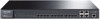
2) When the host port Port2 on the Switch receives this packet, it adds a default VLAN ID 2 to this packet and learns its source MAC address. The MAC address entry, mac_2+VLAN2+Port2 is created, indicating that the egress port for the traffic with destination MAC address mac_2 and VLAN ID 2 is Port2. 3) According to the MAC address duplication, this MAC address entry is copied to VLAN 5, and the switch adds the MAC address entry mac_2+VLAN5+Port2 to its address table. 4) As mac_a is not in the MAC address table of the Switch, the Switch will broadcast this packet in VLAN 2. 5) As the Switch has performed the port configuration synchronization, Port5 can receive this packet from VLAN 2 and forward it to the Router untagged. 6) The Router responds to the Switch upon receiving this packet. 7) When the promiscuous port Port5 receives the response packet, it tags this packet a default VLAN ID 5 and learns the MAC address entry mac_a+VLAN5+Port5. 8) According to the MAC address duplication, this MAC address entry is copied to VLAN 2 and VLAN 3, and the switch adds two more MAC address entries mac_a+VLAN2+Port5 and mac_a+VLAN3+Port5 to its address table. 9) The switch looks up the MAC address table based on mac_2+VLAN5. It finds out the egress port Port2 through which the packet is forwarded to PC2 untagged. After all the steps above are finished, the bidirectional communication between PC2 and the Router is achieved. Private VLAN functions are implemented on the PVLAN and Port Config pages. 6.7.1 PVLAN On this page, you can create Private VLAN and view the information of the current defined Private VLANs. Choose the menu VLAN→Private VLAN→PVLAN to load the following page. Figure 6-14 Create Private VLAN 73
-
 1
1 -
2
-
3
-
4
-
5
-
6
-
7
-
8
-
9
-
10
-
11
-
12
-
13
-
14
-
15
-
16
-
17
-
18
-
19
-
20
-
21
-
22
-
23
-
24
-
25
-
26
-
27
-
28
-
29
-
30
-
31
-
32
-
33
-
34
-
35
-
36
-
37
-
38
-
39
-
40
-
41
-
42
-
43
-
44
-
45
-
46
-
47
-
48
-
49
-
50
-
51
-
52
-
53
-
54
-
55
-
56
-
57
-
58
-
59
-
60
-
61
-
62
-
63
-
64
-
65
-
66
-
67
-
68
-
69
-
70
-
71
-
72
-
73
-
74
-
75
-
76
-
 77
77 -
 78
78 -
 79
79 -
 80
80 -
 81
81 -
 82
82 -
 83
83 -
 84
84 -
 85
85 -
 86
86 -
 87
87 -
88
-
89
-
90
-
91
-
92
-
93
-
94
-
95
-
96
-
97
-
98
-
99
-
100
-
101
-
102
-
103
-
104
-
105
-
106
-
107
-
108
-
109
-
110
-
111
-
112
-
113
-
114
-
115
-
116
-
117
-
118
-
119
-
120
-
121
-
122
-
123
-
124
-
125
-
126
-
127
-
128
-
129
-
130
-
131
-
132
-
133
-
134
-
135
-
136
-
137
-
138
-
139
-
140
-
141
-
142
-
143
-
144
-
145
-
146
-
147
-
148
-
149
-
150
-
151
-
152
-
153
-
154
-
155
-
156
-
157
-
158
-
159
-
160
-
161
-
162
-
163
-
164
-
165
-
166
-
167
-
168
-
169
-
170
-
171
-
172
-
173
-
174
-
175
-
176
-
177
-
178
-
179
-
180
-
181
-
182
-
183
-
184
-
185
-
186
-
187
-
188
-
189
-
190
-
191
-
192
-
193
-
194
-
195
-
196
-
197
-
198
-
199
-
200
-
201
-
202
-
203
-
204
-
205
-
206
-
207
-
208
-
209
-
210
-
211
-
212
-
213
-
214
-
215
-
216
-
217
-
218
-
219
-
220
-
221
-
222
-
223
-
224
-
225
-
226
-
227
-
228
-
229
-
230
-
231
-
232
-
233
-
234
-
235
-
236
-
237
-
238
-
239
-
240
-
241
-
242
-
243
-
244
-
245
-
246
-
247
-
248
-
249
-
250
-
251
-
252
-
253
-
254
-
255
-
256
-
257
 |
 |
