Thermador PRD486GDHU Installation Instructions - Page 15
Step 6: Electrical, Requirements, Connection &, Grounding
 |
View all Thermador PRD486GDHU manuals
Add to My Manuals
Save this manual to your list of manuals |
Page 15 highlights
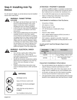
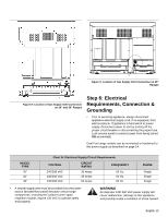
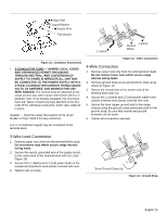
A Figure 9: Location of Gas Supply Inlet Connection on 48" Ranges Figure 8: Location of Gas Supply Inlet Connection on 30" and 36" Ranges Step 6: Electrical Requirements, Connection & Grounding • Prior to servicing appliance, always disconnect appliance electrical supply cord, if so equipped, from wall receptacle. If appliance is hard-wired to power supply, disconnect power to unit by turning off the proper circuit breaker or disconnecting the proper fuse. Lock service panel to prevent power from being turned ON accidentally. Dual Fuel range models can be connected or hardwired to the power supply as described on page 14. MODEL TYPE 30" 36" 48" Chart B: Electrical Supply Circuit Requirements VOLTAGE CIRCUIT RATING FREQUENCY 240/208 VAC 240/208 VAC 240/208 VAC 35 Amps 35 Amps 50 Amps 60 Hz. 60 Hz. 60 Hz. PHASE Single Single Single • A neutral supply wire must be provided from the power source (breaker/fuse panel) because critical range components, including the surface burner spark reignition module, require 120 VAC to operate safely and properly. WARNING An improper 120/ 240 VAC power supply will cause malfunction, damage to this appliance, and possibly create a condition of shock hazard. English 13
-
 1
1 -
2
-
3
-
4
-
5
-
6
-
7
-
8
-
9
-
 10
10 -
 11
11 -
 12
12 -
 13
13 -
 14
14 -
 15
15 -
 16
16 -
 17
17 -
 18
18 -
 19
19 -
 20
20 -
21
-
22
-
23
-
24
-
25
-
26
-
27
-
28
-
29
-
30
-
31
-
32
-
33
-
34
-
35
-
36
-
37
-
38
-
39
-
40
-
41
-
42
-
43
-
44
-
45
-
46
-
47
-
48
-
49
-
50
-
51
-
52
-
53
-
54
-
55
-
56
-
57
-
58
-
59
-
60
-
61
-
62
-
63
-
64
-
65
-
66
-
67
-
68
 |
 |
