Thermador PRD486GDHU Installation Instructions - Page 17
Wire Lead Connection, Wire Connection
 |
View all Thermador PRD486GDHU manuals
Add to My Manuals
Save this manual to your list of manuals |
Page 17 highlights
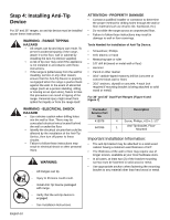
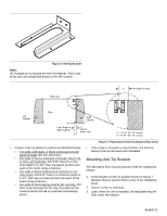
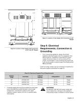
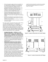
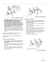
Upper Nut Cupped Washer Supply Wire Flat Washer L1 Black L2 Red Neutral White Figure 12: Conductor Securement • 3-CONDUCTOR CORD - WHERE LOCAL CODES AND ORDINANCES PERMIT GROUNDING THROUGH NEUTRAL, AND CONVERSION OF SUPPLY TO 4 WIRE IS IMPRACTICAL, UNIT MAY BE CONNECTED TO THE POWER SUPPLY WITH A 3-POLE, 3-CONDUCTOR CORD KIT RATED 125/250 VOLTS, 50 AMPERES, AND MARKED FOR USE WITH RANGES. The cord kit must be attached to the range junction box with a strain relief which will fit a 1" diameter hole. If not already equipped, the cord must have 1/4" faston closed-loop lugs attached to the free ends of the individual conductors, prefer-ably soldered in place. Installer - show the owner the location of the circuit breaker or fuse. Mark it for easy reference. A 3- or 4-conductor supply may be connected to the terminal block. Figure 13: 3 Wire Connection 4-Wire Connection 1. Remove upper nuts only from the terminal block studs. Do not remove lower nuts which secure range internal wiring leads. 2. Remove ground strap screw and bend the strap up as shown in Figure 14. 3. Secure the neutral wire to the center stud of the terminal block with nut. 4. Secure the L1 (black) and L2 (red) power leads to the outside terminal studs (brass colored) with nuts. 5. Secure the bare copper ground lead to the range chassis using the ground screw previously used for the ground strap. Be sure that neutral and ground terminals do not touch. 6. Tighten all connections securely. 3-Wire Lead Connection 1. Remove upper nuts only from the terminal block studs. Do not remove nuts which secure range internal wiring leads. 2. Secure the neutral, grounded wire of the supply circuit, to the center stud of the terminal block with nut. (See Figure 13). 3. Secure the L1 (black) and L2 (red) power leads to the outside terminal block studs (brass colored) with nuts. 4. Tighten nuts securely. Bend Ground Strap Up Figure 14: Ground Strap English 15
-
 1
1 -
2
-
3
-
4
-
5
-
6
-
7
-
8
-
9
-
10
-
11
-
 12
12 -
 13
13 -
 14
14 -
 15
15 -
 16
16 -
 17
17 -
 18
18 -
 19
19 -
 20
20 -
 21
21 -
 22
22 -
23
-
24
-
25
-
26
-
27
-
28
-
29
-
30
-
31
-
32
-
33
-
34
-
35
-
36
-
37
-
38
-
39
-
40
-
41
-
42
-
43
-
44
-
45
-
46
-
47
-
48
-
49
-
50
-
51
-
52
-
53
-
54
-
55
-
56
-
57
-
58
-
59
-
60
-
61
-
62
-
63
-
64
-
65
-
66
-
67
-
68
 |
 |
