Thermador PRD486GDHU Installation Instructions - Page 16
With A 3-pole, 4-conductor Cord Kit Rated
 |
View all Thermador PRD486GDHU manuals
Add to My Manuals
Save this manual to your list of manuals |
Page 16 highlights
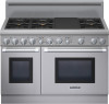
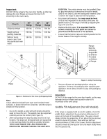
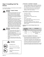
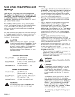
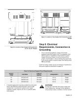
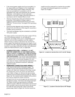
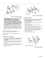
• If the correct power supply circuit is not provided, it is the responsibility and obligation of the installer and user to have proper power supply connected. This must be accomplished in accordance with all applicable local codes and ordinances by a qualified electrician. In the absence of local codes and ordinances, the power supply connection shall be in accordance with the National Electric Code. • Observe all governing codes and ordinances when grounding. In the absence of these codes or ordinances observe National Electrical Code ANSI/ NFPA No. 70 current issue. See page 15 for grounding method. • Electrical wiring diagrams and schematics have been placed in the toe kick area of the range for access by a qualified service technician. • The Dual Fuel Ranges may be connected to a 240/208 VAC power supply. The range must be connected to the power supply utilizing one of the following methods. For all methods of connection, the length of the cord or conduit/wiring must allow the unit to be slid completely out of the cabinet without having to unplug or disconnect the unit from the power supply. Recommended minimum free length of cord or conduit is four feet. Electrical installations and grounding must be in accordance with all local codes and ordinances, and/or the National Electric Code, as applicable. • 4-CONDUCTOR CORD - NORMALLY, A UNIT MUST BE CONNECTED TO THE POWER SUPPLY WITH A 3-POLE, 4-CONDUCTOR CORD KIT RATED 125/250 VOLTS, 50 AMPERES, AND MARKED FOR USE WITH RANGES. The cord kit must be attached to the range junction box with a strain relief which will fit a 1" diameter hole. If not already equipped, the cord must have 1/4" faston closed-loop lugs attached to the free ends of the individual conductors, preferably soldered in place. • PERMANENT CONNECTION (HARD WIRING) - Units may be hard wired to the power supply. The installer must provide approved flexible aluminum conduit, 3/4" trade size, maximum 6 feet long. Locate the junction box on the rear of the unit and remove cover. Refer to Figure 10. Remove the ground strap retaining screw and bend the ground strap up. Refer to Figure 14. The conduit must be installed to the junction box using an approved conduit connector. Wiring for the unit is to be brought into the junction box through the conduit. The ends of the wiring must have 1/4" faston closed-loop lugs attached, preferably soldered in place. Make the connections to the terminal block provided. Secure the ground lead to the junction box with the screw previously used to secure the ground strap. Refer to Figure 13. The free end of the conduit must be connected to a junction box provided in the gas and electrical supply zone, as shown in Figure 3a on page 7. Figure 10: Location of Junction Box on 30" and 36" Ranges Figure 11: Location of Junction Box on 48" Ranges English 14
-
 1
1 -
2
-
3
-
4
-
5
-
6
-
7
-
8
-
9
-
10
-
 11
11 -
 12
12 -
 13
13 -
 14
14 -
 15
15 -
 16
16 -
 17
17 -
 18
18 -
 19
19 -
 20
20 -
 21
21 -
22
-
23
-
24
-
25
-
26
-
27
-
28
-
29
-
30
-
31
-
32
-
33
-
34
-
35
-
36
-
37
-
38
-
39
-
40
-
41
-
42
-
43
-
44
-
45
-
46
-
47
-
48
-
49
-
50
-
51
-
52
-
53
-
54
-
55
-
56
-
57
-
58
-
59
-
60
-
61
-
62
-
63
-
64
-
65
-
66
-
67
-
68
 |
 |
