Thermador PRD486GDHU Installation Instructions - Page 18
Step 7: Backguard Installation
 |
View all Thermador PRD486GDHU manuals
Add to My Manuals
Save this manual to your list of manuals |
Page 18 highlights
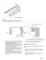
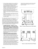
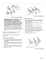
L1 Black L2 Red Ground Wire WARNING • To avoid possible burn or fire hazard, a backguard designed specifically for this range must be installed whenever the range is used. • DO NOT attempt to install a Thermador series backguard, which has air holes in the back panel to supply (only) one cooling fan. [See Figure 16] See Chart C for the correct size of Backguard Kit to match the range. Figure 15: Secure Neutral Wire Step 7: Backguard Installation Front of Range The back panel of backguard is positioned inside these two guide channels on the back of the range. Figure 16: Backguard Positioning WARNING Fingers or hand could get pinched when installing the backguard. Severe injury could result. Use extreme caution and wear thick protective gloves to avoid potential cut or laceration to finger or hand while sliding the backguard down onto the range. • The backguard must be attached before sliding the range into the final, installed position. A Low Back or Pot-and-Pan Shelf must be installed when there is less than 12" clearance from a combustible back wall and the back of the range above the cooking surface. • A Flush Island Trim is included for covering the backguard area of the range for island installations; however, the Flush Island Trim can only be used where there is a minimum of 12" horizontal clearance between a combustible back wall and the back of the range. • The backguard is inserted inside the guide channels on the back of the range, as shown in Figure 16. (Remove the griddle assembly for sufficient installation clearance on models with griddle.) Using a T-20 size Torx driver, fasten the backguard with four (4) Torx-head screws to the range side panels. • The Pot-and-Pan Shelf models require pre-assembly of the top panel to the shell using nine (9) of the enclosed Torx-head screws. For sufficient load strength, YOU MUST attach two (2) screws through the back corners of the top down into the shell. • To secure the front of the back guard, install three (3) of the Torx head screws through the lower front panel of the backguard, into the flange at the back of the range's cooktop. • The Pot-and-Pan Shelf models provide a shelf above the cooktop to keep foods hot or store cooking pans. OBSERVE CAUTIONS CONCERNING ITEMS PLACED ON TOP OF THE SHELF. CAUTION The Pot and Pan Shelf can get very hot! DO NOT place the following items on top of the Pot and Pan Shelf: • plastics or containers that can melt • flammable items • a total load over 30 pounds (13.6kg) English 16
-
 1
1 -
2
-
3
-
4
-
5
-
6
-
7
-
8
-
9
-
10
-
11
-
12
-
 13
13 -
 14
14 -
 15
15 -
 16
16 -
 17
17 -
 18
18 -
 19
19 -
 20
20 -
 21
21 -
 22
22 -
 23
23 -
24
-
25
-
26
-
27
-
28
-
29
-
30
-
31
-
32
-
33
-
34
-
35
-
36
-
37
-
38
-
39
-
40
-
41
-
42
-
43
-
44
-
45
-
46
-
47
-
48
-
49
-
50
-
51
-
52
-
53
-
54
-
55
-
56
-
57
-
58
-
59
-
60
-
61
-
62
-
63
-
64
-
65
-
66
-
67
-
68
 |
 |
