Thermador PRG304GH Installation Instructions - Page 10
Step 3: Unpacking and Moving, the Range - manual
 |
View all Thermador PRG304GH manuals
Add to My Manuals
Save this manual to your list of manuals |
Page 10 highlights
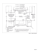
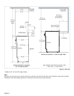
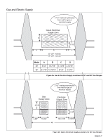
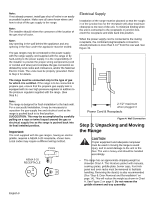
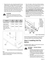
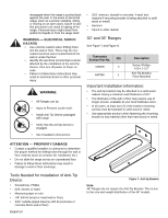
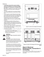
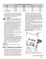
Note: If not already present, install gas shut-off valve in an easily accessible location. Make sure all users know where and how to shut off the gas supply to the range. Note: The installer should inform the consumer of the location of the gas shut-off valve. Note: Any opening in the wall behind the appliance and any opening in the floor under the appliance must be sealed. The gas ranges may be connected to the power supply with the range supply cord supplied with the range or by hard-wiring to the power supply. It is the responsibility of the installer to provide the proper wiring components (cord or conduit and wires) and complete the gas connection as dictated by local codes and ordinances, and/or the National Electric Code. The units must be properly grounded. Refer to Step 6 for details. The range must be connected only to the type of gas for which it is certified. If the range is to be connected to propane gas, ensure that the propane gas supply tank is equipped with its own high pressure regulator in addition to the pressure regulator supplied with the range. (See Step 5.) Note: The range is designed for flush installation to the back wall. For a successful installation, it may be necessary to reposition the gas-supply line and electrical cord as the range is pushed back to its final position. SUGGESTION: This may be accomplished by carefully pulling on a rope or twine looped around the gas or electrical supply line as the range is pushed back into its final installed position. Important: The cord supplied with the gas ranges, having an electric griddle, requires a NEMA 5-20 receptacle, shown here. Local codes may require a different wiring method. PLUG NEMA 5-20 RECEPTACLE Electrical Supply Installation of the range must be planned so that the roughin of the junction box for the receptacle will allow maximum clearance to the rear of the unit. To minimize binding when the unit is connected to the receptacle or junction box, orient the receptacle and slide back into position. When the power supply cord is connected to the mating receptacle, the combined plug/receptacle connection should protrude no more than 2-1/2" from the rear wall. See Figure 3b. 2-1/2" maximum when plugged in Power Cord & Receptacle Figure 4: Wall Connection Step 3: Unpacking and Moving the Range CAUTION Proper equipment and adequate manpower must be used in moving the range to avoid injury, and to avoid damage to the unit or the floor. The unit is heavy and should be handled accordingly. • The range has an approximate shipping weight as shown in Chart A. The literature packet with manuals, cooking grates, griddle plate, burner caps, front kick panel and oven racks must be removed to facilitate handling. Removing the door(s) is also recommended (See "Step 8: Door Removal and Reinstallation" on page 14). This will reduce the weight as shown in Chart A. See Figure 2 on page 6. Do not remove the griddle element and tray assembly. English 8
-
 1
1 -
2
-
3
-
4
-
 5
5 -
 6
6 -
 7
7 -
 8
8 -
 9
9 -
 10
10 -
 11
11 -
 12
12 -
 13
13 -
 14
14 -
 15
15 -
16
-
17
-
18
-
19
-
20
-
21
-
22
-
23
-
24
-
25
-
26
-
27
-
28
-
29
-
30
-
31
-
32
-
33
-
34
-
35
-
36
-
37
-
38
-
39
-
40
-
41
-
42
-
43
-
44
-
45
-
46
-
47
-
48
-
49
-
50
-
51
-
52
-
53
-
54
-
55
-
56
-
57
-
58
-
59
-
60
-
61
-
62
-
63
-
64
 |
 |
