Thermador PRG304GH Installation Instructions - Page 15
Step 7: Backguard Installation - 10
 |
View all Thermador PRG304GH manuals
Add to My Manuals
Save this manual to your list of manuals |
Page 15 highlights
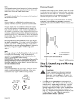
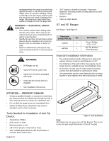
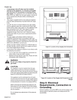
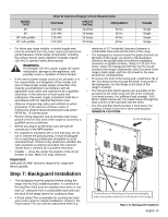
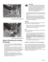
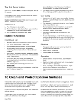
MODEL TYPE 30" 36" 36" with griddle 48" with griddle Chart B: Electrical Supply Circuit Requirements VOLTAGE CIRCUIT RATING FREQUENCY 120 VAC 120 VAC 120 VAC 120 VAC 10 Amps 10 Amps 20 Amps 20 Amps 60 Hz. 60 Hz. 60 Hz. 60 Hz. PHASE Single Single Single Single • For these gas range models, a neutral supply wire must be provided from the power source (breaker/fuse panel) because critical range components, including the surface burner spark reignition modules, require 120 VAC to operate safely and properly. WARNING An improper 120 VAC power supply will cause malfunction, damage to this appliance, and possibly create a condition of shock hazard. • If the correct power supply circuit is not provided, it is the responsibility and obligation of the installer and user to have proper power supply connected. This must be accomplished in accordance with all applicable local codes and ordinances by a qualified electrician. In the absence of local codes and ordinances, the power supply connection shall be in accordance with the National Electrical Code. • Observe all governing codes and ordinances when grounding. In the absence of these codes or ordinances observe National Electrical Code ANSI/ NFPA No. 70 current issue. • Electric wiring diagrams and schematics have been placed in the toe kick area of the range for access by a qualified service technician. • Before you plug in an electrical cord, be sure all controls are in the OFF position. • For appliances equipped with a cord and plug, do not cut or remove the ground prong. It must be plugged into a matching grounding type receptacle to avoid electrical shock. If there is any doubt as to whether the wall receptacle is properly grounded, the customer should have it checked by a qualified electrician. • Installer - show the owner the location of the circuit breaker or fuse. Mark it for easy reference. Important: Dedicated 20 AMP service is required for range with electric griddle. minimum of 12" horizontal clearance between a combustible back wall and the back of the range. • The backguard is inserted inside the guide channels on the back of the range, as shown in the illustration. (Remove the griddle plate for sufficient installation clearance on griddle models.) Using a T-20 size Torx driver, fasten the backguard with four (4) Torx-head screws to the range's side panels, two (2) screws to the range's back panel, and four (4) screws to the area around the cooling blower. • To secure the front of the backguard, install three (3) of the Torx head screws through the lower front panel of the backguard, into the flange at the back of the range's cooktop. • The Pot-and-Pan Shelf requires pre-assembly of the top panel to the shell using nine (9) of the enclosed Torx-head screws. For sufficient load strength, YOU MUST attach the two (2) Torx-head screws through the back corners of the top down into the shell. • The Pot-and-Pan Shelf provides a shelf above the cooktop to keep foods hot or store cooking pans. OBSERVE CAUTIONS. Front of Range Step 7: Backguard Installation • The backguard must be attached before sliding the range into the final, installed position. A Low Back or Pot-and-Pan Shelf must be installed when there is less than 12" clearance from a combustible back wall and the back of the range above the cooking surface. • A Flush Island Trim is available for covering the back area of the range for island installations; however, the Flush Island Trim can only be used where there is a The back panel of backguard is positioned inside these two guide channels on the back of the range. Figure 11: Backguard Installation English 13
-
 1
1 -
2
-
3
-
4
-
5
-
6
-
7
-
8
-
9
-
 10
10 -
 11
11 -
 12
12 -
 13
13 -
 14
14 -
 15
15 -
 16
16 -
 17
17 -
 18
18 -
 19
19 -
 20
20 -
21
-
22
-
23
-
24
-
25
-
26
-
27
-
28
-
29
-
30
-
31
-
32
-
33
-
34
-
35
-
36
-
37
-
38
-
39
-
40
-
41
-
42
-
43
-
44
-
45
-
46
-
47
-
48
-
49
-
50
-
51
-
52
-
53
-
54
-
55
-
56
-
57
-
58
-
59
-
60
-
61
-
62
-
63
-
64
 |
 |
