Tripp Lite APS750 Owner's Manual for DC-to-AC Inverter/Chargers 932803 - Page 3
Feature Identification - inverter
 |
View all Tripp Lite APS750 manuals
Add to My Manuals
Save this manual to your list of manuals |
Page 3 highlights
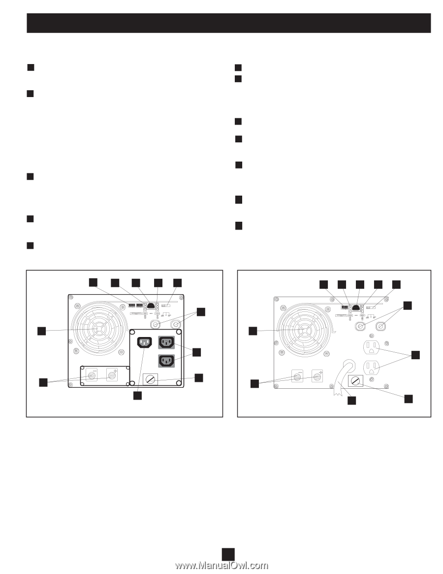
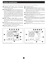
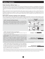
Feature Identification Identify the premium features on your specific model and quickly locate instructions on how to maximize their use. 1 Configuration DIP Switches: optimize Inverter/Charger operation depending on your application. See Configuration section for setting instructions. 2 Operating Mode Switch: controls Inverter/Charger operation. The "AUTO/REMOTE" setting ensures your equipment receives constant, uninterrupted AC power. It also enables the Inverter/ Charger to be remotely monitored and controlled with an optional remote module (Tripp Lite model APSRM4, sold separately). The "CHARGE ONLY" setting allows your batteries to return to full charge faster by turning the inverter off which halts battery discharging. The "DC OFF" setting de-energizes the unit and connects AC OUT to AC IN. See Operation section for setting instructions. 3 "LINE", "INVERT", "LOAD" LEDs: show whether the Inverter/Charger is operating from AC line power or DC battery power. It also warns you if the connected equipment load is too high. See Operation section for instructions on reading the indicator lights. 4 "BATT VOLTAGE" LEDs: these three lights will turn ON in several sequences to show approximate battery level. See Operation section for instructions on reading the indicator lights. 5 DC Power Terminals: connect to your battery terminals. See Battery Connection section for instructions. 6 AC Output Receptacles 7A AC Input Receptacle (230V Models): attach input cord to connect the Inverter/Charger to any source of utility- or generatorsupplied AC power. The user must provide an appropriate country-specific input cable for 230V Models. See AC Input/ Output Connection section for instructions. 7B AC Input Cord (120V Models): plug the Inverter/Charger into a utility- or generator-supplied AC power outlet. 8 Resettable Circuit Breakers: protect your Inverter/Charger against damage due to overload or charger failure. See Operation section for resetting instructions. 9 Remote Control Module Connector: allows remote monitoring and control with an optional module (Tripp Lite model APSRM4, sold separately). See remote module owner's manual for connection instructions. 10 Main Ground Lug: properly grounds the Inverter/Charger to vehicle grounding system or to earth ground. See Configuration section for instructions. 11 Cooling Fan: quiet, efficient fan prolongs equipment service life. 1 4 9 3 2 8 11 6 10 5 7A Front View (230V Non-Corded Models) 1 4 9 3 2 8 11 6 5 7B 10 Front View (120V Corded Models) 3
-
 1
1 -
 2
2 -
 3
3 -
 4
4 -
 5
5 -
 6
6 -
 7
7 -
 8
8 -
 9
9 -
10
-
11
-
12
-
13
-
14
-
15
-
16
-
17
-
18
-
19
-
20
-
21
-
22
-
23
-
24
-
25
-
26
-
27
-
28
-
29
-
30
-
31
-
32
-
33
-
34
-
35
-
36
-
37
-
38
-
39
-
40
-
41
-
42
-
43
-
44
-
45
 |
 |