Tripp Lite BP480V65 Owners Manual for Extended-Run Battery Cabinet English - Page 10
Final Electrical Check
 |
View all Tripp Lite BP480V65 manuals
Add to My Manuals
Save this manual to your list of manuals |
Page 10 highlights
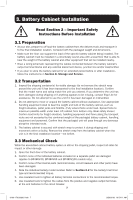
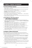
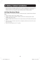
3. Battery Cabinet Installation 7. Feed the positive and negative cables (and "N" center, if equipped) from the open external disconnect switch or the UPS battery field wiring terminals through the conduit/cable bushing. Connect to the respective output terminals inside the battery cabinet. 3.8 Final Electrical Check Before closing any connecting circuit breaker or disconnect switch, complete these verification steps: 1. Verify the battery cabinet output voltage is correct. 2. If battery cabinets will be operated in parallel, verify that the individual system output voltages match within 2V DC. 3. Verify the voltage measured between either output terminal and the battery cabinet ground is zero. 4. If any of the above verification steps show an irregularity, determine and correct the cause before proceeding. 5. Reset the circuit breaker to the "On" position. 10 18-09-176-933861.indb 10 9/26/2018 10:54:11 AM
-
 1
1 -
2
-
3
-
4
-
 5
5 -
 6
6 -
 7
7 -
 8
8 -
 9
9 -
 10
10 -
 11
11 -
 12
12 -
 13
13 -
 14
14 -
 15
15 -
16
-
17
-
18
-
19
-
20
-
21
-
22
-
23
-
24
-
25
-
26
-
27
-
28
-
29
-
30
-
31
-
32
-
33
-
34
-
35
-
36
-
37
-
38
-
39
-
40
-
41
-
42
-
43
-
44
-
45
-
46
-
47
-
48
-
49
-
50
-
51
-
52
-
53
-
54
-
55
-
56
-
57
-
58
-
59
-
60
-
61
-
62
-
63
-
64
-
65
-
66
-
67
-
68
-
69
-
70
-
71
-
72
-
73
-
74
-
75
-
76
-
77
-
78
-
79
-
80
-
81
-
82
-
83
-
84
-
85
-
86
-
87
-
88
-
89
-
90
-
91
-
92
-
93
-
94
-
95
-
96
-
97
-
98
-
99
-
100
-
101
-
102
-
103
-
104
-
105
-
106
-
107
-
108
-
109
-
110
-
111
-
112
-
113
-
114
-
115
-
116
-
117
-
118
-
119
-
120
-
121
-
122
-
123
-
124
-
125
-
126
-
127
-
128
-
129
-
130
-
131
-
132
-
133
-
134
-
135
-
136
-
137
-
138
-
139
-
140
-
141
-
142
-
143
-
144
-
145
-
146
-
147
-
148
-
149
-
150
-
151
-
152
-
153
-
154
-
155
-
156
-
157
-
158
-
159
-
160
-
161
-
162
-
163
-
164
-
165
-
166
-
167
-
168
-
169
-
170
-
171
-
172
-
173
-
174
-
175
-
176
 |
 |
