Tripp Lite BP480V65 Owners Manual for Extended-Run Battery Cabinet English - Page 8
Internal Wiring Typical, 5 Preliminary Electrical Check, After Battery Installation, 6 Battery
 |
View all Tripp Lite BP480V65 manuals
Add to My Manuals
Save this manual to your list of manuals |
Page 8 highlights
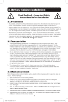
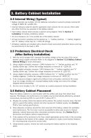
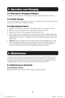
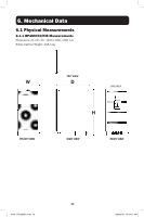
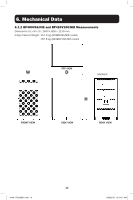
3. Battery Cabinet Installation 3.4 Internal Wiring (Typical) • Battery cabinets use multiple 12V DC batteries connected in series to provide nominal DC voltage of 480V DC (±240V DC). • Internal cabling is sized for specific application load currents. Do not use any other cable size other than the one provided in the battery cabinet. • Each battery cabinet shelf includes a specific wiring diagram. Refer to Section 7. Installation for battery installation details. • All circuit breakers are in the middle tier of the battery cabinet. • All load connection polarities will be labeled as "+" (battery positive), "-" (battery negative) and "N" (battery center tap) for ±240V DC strings. • All battery cabinets are provided with a branch circuit overcurrent protection device and may be wired directly to the load or UPS. 3.5 Preliminary Electrical Check (After Battery Installation) 1. With the circuit breaker OFF, measure the battery voltage at the line side of the circuit breaker using a digital voltmeter. Refer to the diagrams in Section 7.2.3 Battery Cabinet Internal Wiring for more information. 2. Using a digital voltmeter, measure +240V between the "+" (battery positive) and "N" (battery center tap). Confirm the voltage measures a minimum of +220V DC. 3. Using a digital voltmeter, measure -240V between the "-" (battery negative) and "N" (battery center tap). Confirm the voltage measures a minimum of -220V DC. 4. Using a digital voltmeter, measure +480V between the "+" (battery positive) and the "-" (battery negative). Confirm the voltage measures a minimum of +440V DC. 5. If the measured voltage is significantly different than anticipated, determine the cause (e.g. low charge, shorted cell, reversed battery, faulty wiring) and correct the voltage disparity before proceeding. 6. Set the circuit breaker to the "off" position as a safety precaution during installation. 3.6 Battery Cabinet Placement Place the battery cabinet in a cool location with free airflow and away from direct heat sources. The lifespan and performance of a battery may be dramatically affected by elevated temperature, decreasing 50% for each 8.25° C above 25° C. 1. Prepare the surface where the cabinet will be placed. The surface must be clean, flat and able to support the battery cabinet and other equipment installed nearby. See Section 7.4 for floor loading specifications. 2. Allow adequate clearance around the front and rear of the battery cabinet for ventilation and maintenance. The front door must be accessible to allow easy access to internal batteries, internal fuses and other overcurrent protection devices. See Section 6.1 for dimensions and battery cabinet measurements. 3. If the cabinet will be anchored to the floor, install appropriate anchor bolts in the mounting hole located at the bottom of the cabinet. Use washers to create a level surface between the mounting areas around the anchor bolts. 4. Using extreme caution, remove the bolts securing the battery cabinet to the shipping pallet. 8 18-09-176-933861.indb 8 9/26/2018 10:54:11 AM
-
 1
1 -
2
-
 3
3 -
 4
4 -
 5
5 -
 6
6 -
 7
7 -
 8
8 -
 9
9 -
 10
10 -
 11
11 -
 12
12 -
 13
13 -
14
-
15
-
16
-
17
-
18
-
19
-
20
-
21
-
22
-
23
-
24
-
25
-
26
-
27
-
28
-
29
-
30
-
31
-
32
-
33
-
34
-
35
-
36
-
37
-
38
-
39
-
40
-
41
-
42
-
43
-
44
-
45
-
46
-
47
-
48
-
49
-
50
-
51
-
52
-
53
-
54
-
55
-
56
-
57
-
58
-
59
-
60
-
61
-
62
-
63
-
64
-
65
-
66
-
67
-
68
-
69
-
70
-
71
-
72
-
73
-
74
-
75
-
76
-
77
-
78
-
79
-
80
-
81
-
82
-
83
-
84
-
85
-
86
-
87
-
88
-
89
-
90
-
91
-
92
-
93
-
94
-
95
-
96
-
97
-
98
-
99
-
100
-
101
-
102
-
103
-
104
-
105
-
106
-
107
-
108
-
109
-
110
-
111
-
112
-
113
-
114
-
115
-
116
-
117
-
118
-
119
-
120
-
121
-
122
-
123
-
124
-
125
-
126
-
127
-
128
-
129
-
130
-
131
-
132
-
133
-
134
-
135
-
136
-
137
-
138
-
139
-
140
-
141
-
142
-
143
-
144
-
145
-
146
-
147
-
148
-
149
-
150
-
151
-
152
-
153
-
154
-
155
-
156
-
157
-
158
-
159
-
160
-
161
-
162
-
163
-
164
-
165
-
166
-
167
-
168
-
169
-
170
-
171
-
172
-
173
-
174
-
175
-
176
 |
 |