Tripp Lite BP480V65 Owners Manual for Extended-Run Battery Cabinet English - Page 9
Electrical Connection
 |
View all Tripp Lite BP480V65 manuals
Add to My Manuals
Save this manual to your list of manuals |
Page 9 highlights
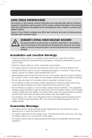
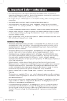
3. Battery Cabinet Installation 5. Forklift forks should be at maximum width within the cabinet clearance opening and fully inserted to prevent tipping. Lift cabinet from bottom only. Be careful not to damage the sheet metal floor of the cabinet with the forks. 6. If the battery cabinet will be secured to the floor, carefully align and lower the battery cabinet down on the floor anchor bolts and secure it in place. 7. If the cabinet will not be secured to the floor, lower it into the designated space and then level it using shims. Leveling does not affect performance, but does align the battery cabinet with other equipment in the facility. 3.7 Electrical Connection DANGER! LETHAL HIGH-VOLTAGE HAZARD! All wiring should be performed by a qualified electrician in accordance with the warnings in this manual and all applicable electrical and safety codes. Incorrect wiring may cause serious personal injury and property damage. • The battery cabinet is connected to the load through a DC circuit breaker. This allows the battery to disconnect from the load and charger for maintenance and/or repair. • The DC molded case circuit breakers are CE-approved for branch circuit protection. If replacement is required, CE-approved components with the same voltage and current rating must be used. • The size of the load connection cables must consider maximum allowable voltage drop, as well as the cables' continuous ampere capacity and anticipated ampere discharge rate of the individual battery cabinet. A maximum voltage drop of 1.5V DC in the load connection cables is recommended. Refer to the UPS unit's Owner's Manual for recommended wire sizes. • Refer to all applicable local, state and national codes for appropriate cable size and ratings. • External circuit protection devices (fuses or circuit breakers) must consider the discharge rate of the battery, the wiring to be protected and the DC short circuit current of the battery. After performing the installation procedures in Section 7.: 1. Open the front door of the battery cabinet to access internal components. Use a digital voltmeter when voltage measurements are required. 2. Determine if the battery has been inadvertently grounded by resetting the circuit breaker to the "On" position and measuring the voltage between the battery cabinet grounding lug and the positive load connection point within the cabinet. This voltage should measure 0 (zero) VDC. If the measured voltage is not zero, determine the cause and correct before proceeding. 3. Return the internal circuit breaker to an open "Off" position as a safety precaution while connecting the output cables. Doing so prevents damage in the event the cables are accidentally shorted. 4. The top of the battery cabinet includes knockouts for load connection cable entry. Punch out the appropriate knockout and connect the conduit or cable bushing. 5. The output circuit breaker accommodates cables up to 300 mm2. 6. Connect an appropriate equipment grounding cable to the grounding lug located on the top of the battery cabinet. 9 18-09-176-933861.indb 9 9/26/2018 10:54:11 AM
-
 1
1 -
2
-
3
-
 4
4 -
 5
5 -
 6
6 -
 7
7 -
 8
8 -
 9
9 -
 10
10 -
 11
11 -
 12
12 -
 13
13 -
 14
14 -
15
-
16
-
17
-
18
-
19
-
20
-
21
-
22
-
23
-
24
-
25
-
26
-
27
-
28
-
29
-
30
-
31
-
32
-
33
-
34
-
35
-
36
-
37
-
38
-
39
-
40
-
41
-
42
-
43
-
44
-
45
-
46
-
47
-
48
-
49
-
50
-
51
-
52
-
53
-
54
-
55
-
56
-
57
-
58
-
59
-
60
-
61
-
62
-
63
-
64
-
65
-
66
-
67
-
68
-
69
-
70
-
71
-
72
-
73
-
74
-
75
-
76
-
77
-
78
-
79
-
80
-
81
-
82
-
83
-
84
-
85
-
86
-
87
-
88
-
89
-
90
-
91
-
92
-
93
-
94
-
95
-
96
-
97
-
98
-
99
-
100
-
101
-
102
-
103
-
104
-
105
-
106
-
107
-
108
-
109
-
110
-
111
-
112
-
113
-
114
-
115
-
116
-
117
-
118
-
119
-
120
-
121
-
122
-
123
-
124
-
125
-
126
-
127
-
128
-
129
-
130
-
131
-
132
-
133
-
134
-
135
-
136
-
137
-
138
-
139
-
140
-
141
-
142
-
143
-
144
-
145
-
146
-
147
-
148
-
149
-
150
-
151
-
152
-
153
-
154
-
155
-
156
-
157
-
158
-
159
-
160
-
161
-
162
-
163
-
164
-
165
-
166
-
167
-
168
-
169
-
170
-
171
-
172
-
173
-
174
-
175
-
176
 |
 |
