URC DMS-AV Owners Manual - Page 12
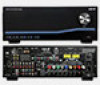
DMS-AV Rear Panel
 |
View all URC DMS-AV manuals
Add to My Manuals
Save this manual to your list of manuals |
Page 12 highlights
DMS-AV HOME THEATER AMPLIFIER DMS-AV Rear Panel 1 2 3 4 5 678 9 10 11 12 13 1. Voltage Triggers, Reset Switch and Ethernet - The two 12 volt triggers present at this section of the back panel supply a maximum current of 100 mA, and can be used to trigger an external amplifier, or can also be used to trigger the use of an anamorphic lens on a projector. These jacks are both 3.5 mm mono style female mini jacks. The pin is positive(+), and the sleeve is ground. Each of the 12V DC triggers may be set to 12V DC when a particular input is selected. For example, Trigger #1 may be set to output 12V DC when Input 8 is selected. When another input besides Input 8 is selected, Trigger #1 will go to 0V DC. The Ethernet port is a 10/100 Base Ethernet port, that allows receiving and sending multicast audio streams when used with a DMS/SNP URC Multi zone system, and also used for command and control when used with an MRX-10/MRX-12 (or similar) URC Advanced System Controller. Pressing the RESET button will return the DMS-AV to its factory default state. 2. Optical and Coaxial Digital S/PDIF Inputs/Output - By default, the optical and coaxial S/PDIF audio inputs are not assigned to any composite, component or HDMI video input. The optical and coaxial S/PDIF inputs require assignment to a video input (via the on-screen display, or the URC Accelerator PC application). Any of the optical/coaxial S/PDIF inputs can be assigned to any numbered video input (Composite, Component or HDMI). The optical/coaxial S/PDIF inputs cannot be assigned to Input Phono or Input Multi Cast Stream, since those inputs are "Audio Only" inputs. The optical digital output shall provide a S/PDIF digital output of any selected optical input signal. This digital output is for use with a digital recording device. Page 13
-
 1
1 -
2
-
3
-
4
-
5
-
6
-
 7
7 -
 8
8 -
 9
9 -
 10
10 -
 11
11 -
 12
12 -
 13
13 -
 14
14 -
 15
15 -
 16
16 -
 17
17 -
18
-
19
-
20
-
21
-
22
-
23
-
24
-
25
-
26
-
27
-
28
-
29
-
30
-
31
-
32
-
33
-
34
-
35
-
36
-
37
-
38
-
39
-
40
-
41
-
42
-
43
-
44
-
45
-
46
-
47
-
48
-
49
-
50
 |
 |
