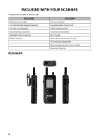
Uniden BCD436HP English Owner's Manual - Page 18
Base Station - scanner antenna
 |
View all Uniden BCD436HP manuals
Add to My Manuals
Save this manual to your list of manuals |
Page 18 highlights
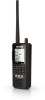
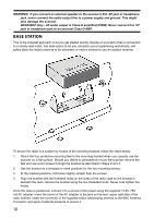
WARNING! If you connect an external speaker to the scanner's Ext. SP jack or headphone jack, never connect the audio output line to a power supply and ground. This might also damage the scanner. BCD536HP Only - All audio output is Class-D amplified (PWM). Never connect Ext. SP jack or headphone jack to an external Class-D AMP. Base Station This is the simplest approach to let you get started quickly. Decide on a location that is convenient to a nearby wall outlet, has desk space to let you complete your programming worksheets, will safely allow the indoor antenna to be extended, or near a window to use an outdoor antenna. To secure the radio to a surface by means of the mounting bracket, follow the steps below: 1. Attach the four protective mounting feet to the mounting bracket when you casually use the scanner on a flat surface. Should you desire to permanently mount the scanner, remove the feet and use wood screws through the bracket as described in Steps 2 and 3. 2. Use the bracket as a template to mark positions for the two mounting screws. 3. At the marked positions, drill holes slightly smaller than the screws. 4. Align the bracket with the threaded holes on the sides of the radio case so the bracket is beneath the radio. Secure the bracket using the two threaded knobs. Never over tighten the knobs. Once the radio is positioned, connect it to a source of AC power using the supplied 13.8V, 750 mA AC adapter. Insert the barrel of the AC adapter to the jack on the rear, upper right side of the radio marked. Insert the connector of the supplied indoor telescoping antenna to the BNC Antenna Connector and apply moderate pressure to secure it. 10
-
 1
1 -
2
-
3
-
4
-
5
-
6
-
7
-
8
-
9
-
10
-
11
-
12
-
 13
13 -
 14
14 -
 15
15 -
 16
16 -
 17
17 -
 18
18 -
 19
19 -
 20
20 -
 21
21 -
 22
22 -
 23
23 -
24
-
25
-
26
-
27
-
28
-
29
-
30
-
31
-
32
-
33
-
34
-
35
-
36
-
37
-
38
-
39
-
40
-
41
-
42
-
43
-
44
-
45
-
46
-
47
-
48
-
49
-
50
-
51
-
52
-
53
-
54
-
55
-
56
-
57
-
58
-
59
-
60
-
61
-
62
-
63
-
64
-
65
-
66
-
67
-
68
-
69
-
70
-
71
-
72
-
73
-
74
-
75
-
76
-
77
-
78
-
79
-
80
-
81
-
82
-
83
-
84
-
85
-
86
-
87
-
88
-
89
-
90
-
91
-
92
-
93
-
94
-
95
-
96
-
97
-
98
-
99
-
100
-
101
-
102
-
103
-
104
 |
 |
