ViewSonic PJD7325 PJD6252L User Guide English - Page 18
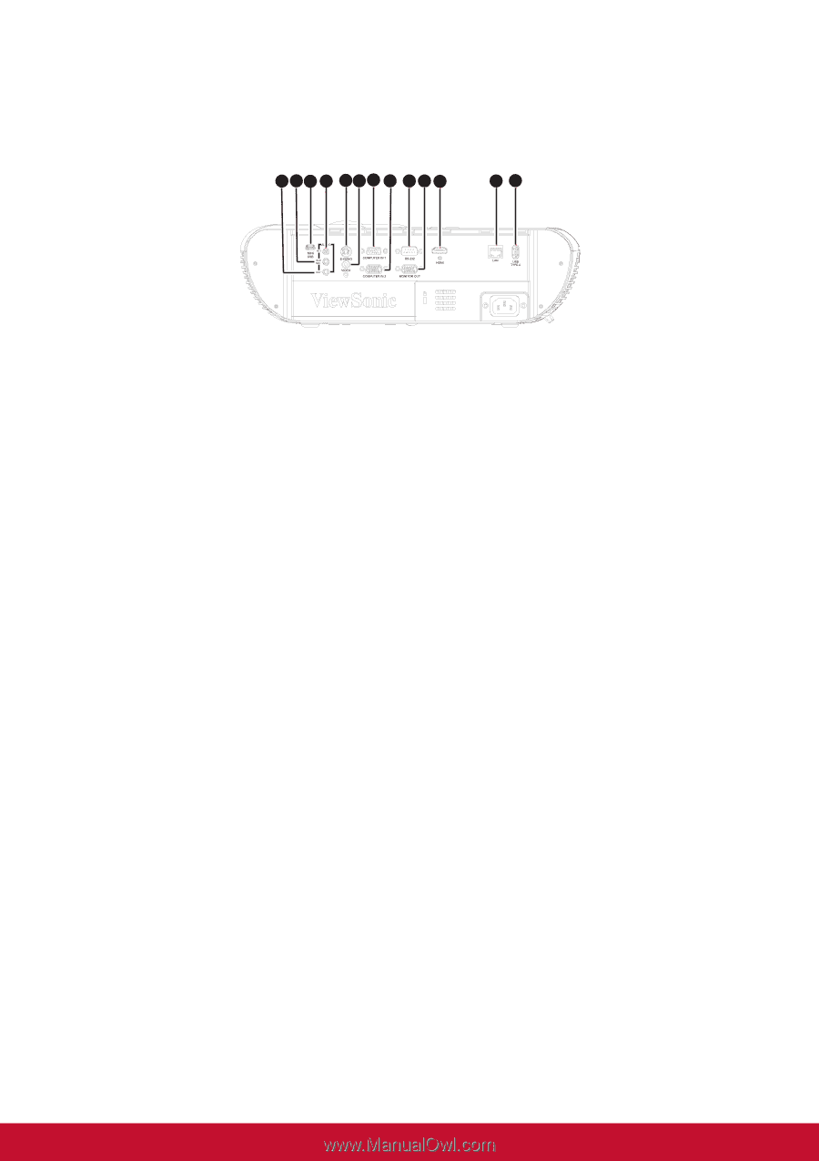
Connection Ports, Audio Out, Audio In 2 / Mic, Mini Usb, Audio In 1, S-video, Computer In 1, Rs-232
 |
View all ViewSonic PJD7325 manuals
Add to My Manuals
Save this manual to your list of manuals |
Page 18 highlights
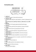
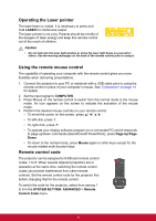
Connection ports 1 2 3 4 5 6 7 8 9 10 11 12 13 1. AUDIO OUT Connect to a speaker or other audio input equipment. 2. AUDIO IN 2 / MIC Connect an audio output from video equipment / computer or Microphone to this jack. Note: The function for switching to Audio in 2 / Microphone in is in OSD menu. 3. MINI USB This connector is for firmware update and mouse function support. 4. AUDIO IN 1 Connect an audio output from video equipment or computer to this jack. 5. S-VIDEO Connect S-Video output from video equipment to this jack. 6. VIDEO Connect composite video output from video equipment to this jack. 7. COMPUTER IN 1 Connect image input signal (analog RGB or component) to this jack. 8. COMPUTER IN 2 Connect image input signal (analog RGB or component) to this jack. 9. RS-232 When operating the projector via a computer, connect this to the controlling computer's RS-232C port. 10. MONITOR OUT Connect to a computer display, etc. 11. HDMI Connect HDMI output from video equipment to this jack. 12. LAN RJ45 connector for Ethernet connection. 13. USB TYPE A 5V/2A out for power charging. 7
-
 1
1 -
2
-
3
-
4
-
5
-
6
-
7
-
8
-
9
-
10
-
11
-
12
-
 13
13 -
 14
14 -
 15
15 -
 16
16 -
 17
17 -
 18
18 -
 19
19 -
 20
20 -
 21
21 -
 22
22 -
 23
23 -
24
-
25
-
26
-
27
-
28
-
29
-
30
-
31
-
32
-
33
-
34
-
35
-
36
-
37
-
38
-
39
-
40
-
41
-
42
-
43
-
44
-
45
-
46
-
47
-
48
-
49
-
50
-
51
-
52
-
53
-
54
-
55
-
56
-
57
-
58
-
59
-
60
-
61
-
62
-
63
-
64
-
65
-
66
-
67
-
68
-
69
-
70
-
71
-
72
-
73
-
74
-
75
-
76
-
77
-
78
-
79
-
80
-
81
-
82
-
83
-
84
-
85
-
86
-
87
 |
 |