Viking RDMOS201SS 30 inch W. Built-In Trim Kit - Installation Instructions - Page 4
General Information
 |
View all Viking RDMOS201SS manuals
Add to My Manuals
Save this manual to your list of manuals |
Page 4 highlights
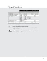
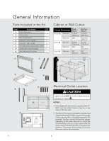
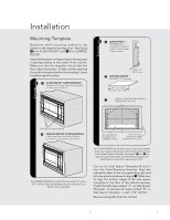
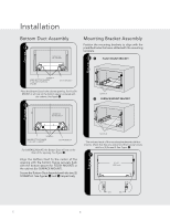
General Information Par ts Included in the Kit 1) Frame Assembly: QTY 1 Cabinet or Wall Cutout 2) Bottom Duct Assembly: QTY 1 Item 1 2 3 4 5 6 7 Part Name QTY Frame Assembly 1 Bottom Duct 1 Mounting Bracket 2 Screw A :1-3/16" length 2 Screw B: 1-3/4" length 4 Side Decoration (Surface Mount Only) 2 Surface Mounting Template 1 Cutout Dimensions Height A Minimum Maximum Width B Minimum Maximum Flush Mount 17-5/16" (439.8mm) N/A 29-5/8" (752.5mm) N/A Surface Mount 16-9/16" (420.7mm) 16-13/16" (427mm) 27-3/4" (704.9mm) 28" (711.2mm) 8 1F) Flruasmhe AMssoemunbltyi:nQgTYT1emplate 3) Mouting 1 Bracket: Q2)TBYo2ttom DucDt eApsstehmbCly: QTY M1 inimum4()SSUIRDFEADC2(EE5C0M0O"O3RmUANTmITOINN) G: QOTNYL2(2Y50)0"3mm) 2) Bottom Duct Assembly: QTY 1 1 3 1 4"(10.2 cm) 6"(15.2 cm) figure 1 2) Bottom Duct Assembly: QTY 1 2 4 4"(10.2 cm) 3) Mouting Bracket: QTY 2 4) SIDE DECORATION: QTY 2 (SURFACE MOUNTING ONLY) 4) SIDE DECORATION: QTY 2 (SURFACE MOUNTING ONLY) 5 6 2 4) SIDE DECOR7 ATION: QTY 2 (SURFACE MOUNTING ONLY) Maximum Cutout Opening Width 28" (711.2 mm) Minimum Cutout Opening Width 27-3/4" (704.9 mm) Electrical Outlet Location CAUTION Outlet should NOT be in the shaded area as indicated on figure 1. Minimum Cutout Opening Height 16-9/16" (420.7 mm) Maximum Cutout Opening Height 16-13/16" (427 mm) Distance between holes A9.1" (231.2 mm) BUILT-IN TRIM KIT SURFACE MOUNTING TEMPLATE FOR DESIGNER SERIES MICROWAVE OVEN Center Line 1. Align the Surface Mounting Template center line with the center of the cabinet. Align the Floor Line with the bottom of the cabinet at the desired height. Tape it into place. 2. Predrill 4 holes marked A with a drill bit. 3. Cut the cabinet opening between the minimum and maximum cutout opening lines. Be careful to cut precisely along the Floor Line of the cutout. 4. Remove template from the cabinet. 3-15/16" (100 mm) 14-1/4" (361.95 mm) 1/4" (6.2 mm) 14" (355.6 mm) Floor Line of Cutout Opening 8 Cutout Opening Width 29-5/8" (752.5 mm) CABINET CUTOUT LINE CABINET CUTOUT LINE CABINET CUTOUT LINE SIDE SPACER TEMPLATE - L Align Side Spacer-L to this line 13-1/2" min. height Edges to align Side Spacer Templates (R and L) 13/16" Min. 15/16 Max. FIGURE 1 Side Spacer (2 required) Must protrude from edge of cabinet cutout towards center as shown. 24" min. width 27-7/8" max. width FIGURE 2 Bottom Spacer (1 required) ¹₄" plywood Side Spacer - L Side Spacer - R Bottom Spacer centered with cabinet cutout FIGURE 3 1-9/16" (39.7 mm) Bottom and Side Spacer (R and L) Offset 1/4" (6.35 mm) 14" (355.9 mm) 14-13/16" (376.2 mm) FLOOR LINE OF CUTOUT OPENING CENTER LINE BUILT-IN TRIM KIT FLUSH MOUNTING TEMPLATE FOR DESIGNER SERIES MICROWAVE OVEN 1. Align the Flush Mounting Template center line with the center of the cabinet. Align the Floor Line with the bottom of the cabinet at the desired height. Tape it in place. 2. Cut the cabinet opening along the three Cabinet Cutout Lines and the Floor Line. 3. Install two Side Spacers (see FIGURE 1) and one Bottom Spacer (see FIGURE 2) as specified in FIGURE 3. Be sure to offset all three spacers by 1 from the front surface of the cabinet. 4. Cut out the Side Spacer Templates (R and L) and align the indicated edge to the corresponding Side Spacer (see FIGURE 3). Be careful to align the Floor Line to the bottom edges of the Side Spacers. 5. Predrill two holes indicated "A" in Side Spacer - R with a drill bit. 6. Predrill two holes indicated "B" in Side Spacer - L with a drill bit. 7. Remove template from the cabinet. 4-3/16" (106.4 mm) 1/4" (6.35 mm) TINSLB009MRR0 Distance between holes A9.1" (231.2 mm) Cutout Opening Height 17-5/16" (439.8 mm) Align Side Spacer-R to this line SIDE SPACER TEMPLATE - R TINSLB008MRR0 1/4" (6.2 mm) NOTES: • If the Depth (C) dimension is greater than 21" (53.3 cm), the outlet location may be in any area on the rear wall. • The floor of the opening should be constructed of plywood strong enough to support the weight of the oven and floor load (approximately 100 pounds). The floor should be level for proper operation of the oven. Be sure to check the local building code as it may require that the opening be enclosed with side, ceiling and rear partition. The proper functioning of the oven does not require the enclosure. E 4
-
 1
1 -
 2
2 -
 3
3 -
 4
4 -
 5
5 -
 6
6 -
 7
7 -
 8
8 -
 9
9 -
 10
10 -
11
-
12
-
13
-
14
-
15
-
16
-
17
-
18
-
19
-
20
-
21
-
22
-
23
-
24
 |
 |
