Viking RDMOS201SS 30 inch W. Built-In Trim Kit - Installation Instructions - Page 5
Installation
 |
View all Viking RDMOS201SS manuals
Add to My Manuals
Save this manual to your list of manuals |
Page 5 highlights
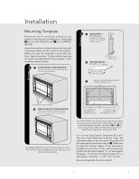
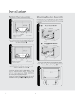
figure figure 13-1/2" min. Installation Mounting Template Determine which mounting method to use based on the required configuration. See figure 2A for FLUSH Mount and 2B for SURFACE Mount. Align the template corresponding to the required mounting method to the center of the cabinet. Make sure that the template is level with the floor. Tape it into place. Cut the cabinet opening along the lines specified on the template. Leave template taped Illustration 2 in place. 2 a. Flush Mount Configuration Microwave Oven and Frame Assembly A glaFsslaure sfluhsh wmithothue cnabtinect onfiguration- Microwave Oven and Frame Assembly glass are flush with the cabinet. 3 A SIDE SPACER-2 REQUIRED. Must protrude from edge of cabinet cutout towards center as shown. 13/16" min. 15/16" max. B BOTTOM SPACER-1 REQUIRED. 1/4" plywood. 24" min. width 27-7/8" max. width C EDGES TO ALIGN SIDE SPACER TEMPLATES (R and L) Side Spacer (L) Side Spacer (R) Indicated surfaces are flush. b. Surface Mount Configuration - B Microwave Oven and Frame Assembly SpUrotRrudFeAfroCmEthemsuorfacue onf thte ccaboinent. figuration -Microwave Oven and Frame Assembly protrude from the surface of the cabinet. BOTTOM SPACER CENTERED with CABINET CUTOUT 1-9/16" (39.7 mm) BOTTOM and SIDE SPACER (R and L) offset For Surface Mount, predrill 4 holes marked "A" with a 1/16" drill bit. Remove template from the cabinet. Go to Bottom Duct Assembly. For Flush Mount, two (2) side spacers and one (1) bottom spacer are required. Spacers are not included in the kit and must be fabricated by installer. See figures 3A and B for spacer requirements. Make sure that all three spacers are offset from the front of the cabinet by 1-9/16". Cut out the Side Spacer Templates (R and L) from the Flush Mounting Template. Align the indicated edges to the corresponding right and left side spacers as shown in figure 3. Make sure to align the bottom edges of the side spacer templates to the floor of the cabinet opening. Predrill two (2) holes marked "A" on Side Spacer Template - R and two (2) holes marked "B" on Side Spacer Template - L with 1/16" drill bit. Remove templates from the cabinet. 5 E
-
 1
1 -
 2
2 -
 3
3 -
 4
4 -
 5
5 -
 6
6 -
 7
7 -
 8
8 -
 9
9 -
 10
10 -
 11
11 -
12
-
13
-
14
-
15
-
16
-
17
-
18
-
19
-
20
-
21
-
22
-
23
-
24
 |
 |
