Viking RDMOS201SS 30 inch W. Built-In Trim Kit - Installation Instructions - Page 7
Cabinet Installation, Frame Assembly
 |
View all Viking RDMOS201SS manuals
Add to My Manuals
Save this manual to your list of manuals |
Page 7 highlights
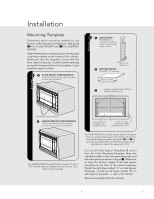
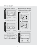
STALL Installation Align the mounting brackets horizontally by sliding them back and forth along the screw slots until the brackets are exactly 27-1/2" apart and equal distance from the cabinet sides. See figure 7. Once the brackets are correctly positioned, securely tighten the four (4) screws B. Cabinet InCsAtaBlIlNatEiTonINSTALL Place the oven adjacent to the wall or cabinet opening. Plug the power cord into the electrical outlet. 8 figure Frame Assembly Turn over FRAME ASSEMBLY to locate the 4 ball studs. ! 4 BALL STUDS On BACK OF FRAME ASSEMBLY SMALL STAINLESS DECORATIONS ON TOP figure figure CABINET INSTALL Carefully guide the assembled oven into the prepared opening. Slide the oven onto the Bottom Duct Assembly. See figure 8. 9 FOOT BOTTOM DUCT ASSEMBLY DUCT RECESS FRAME INSTALL SNAP ATTACHMENT LOCATIONS ON MOUNTING BRACKETS Position the FRAME ASSEMBLY with the small stainless decorations on top. Align the 4 ball studs with the 4 snap attachments at both ends of the MOUNTING BRACKETS. Secure the FRAME ASSEMBLY by firmly pushing it onto the mounting brackets engaging the four (4) snap attachments. See Figure !. Avoid pinching the cord between the oven and the wall. Adjust the position of the oven so that the feet of the oven are fitted into the recesses of the Bottom Duct Assembly. See figure 9. 7 E
-
 1
1 -
 2
2 -
 3
3 -
 4
4 -
 5
5 -
 6
6 -
 7
7 -
 8
8 -
 9
9 -
 10
10 -
 11
11 -
 12
12 -
13
-
14
-
15
-
16
-
17
-
18
-
19
-
20
-
21
-
22
-
23
-
24
 |
 |
