Viking RDSCE2305BSS Installation Instructions - Page 12
Final Installation, Door Replacement and Adjustment
 |
View all Viking RDSCE2305BSS manuals
Add to My Manuals
Save this manual to your list of manuals |
Page 12 highlights
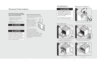
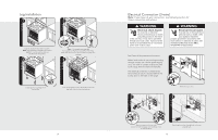
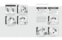
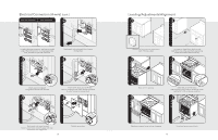
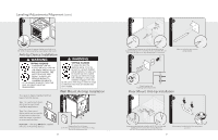
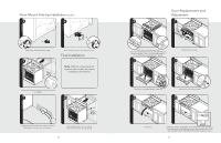
Floor Mount Anti-tip Installation (cont.) 3 4 1 2 x2 Remove two screws from back of range. 5 1 2 Attach bracket to back of range using two screws. Final Installation Note: Refer to range electrical requirements section for proper installation information. Slide range into place and check that hook and bracket are engaged. 1 2 Connect electrical in shaded area. See the "Electrical Requirements" section for more information. Slide range into place. Be sure anti-tip bracket slides into the anit-tip opening. 22 Door Replacement and Adjustment 3 1 (03.9/58"cm) Check that unit is level side to side and front to back. The side trim must be 3/8" (0.95 cm) above countertop. If unit is not level repeat steps 5-7 of "Leveling/Adjustments/Alignment" section. 2 Reattach door to range. 3 2 1 2 3 Open door completely. Reattach hinge trim. 4 Remove pins from hole in hinges. 5 Close door. If the door needs to be adjusted, loosen hinge trim screws (see step 2). Adjust the screws located between the door and kickplate using a 5/32" hex head allen wrench. After adjustment, tighten hinge trim screws. 23
-
 1
1 -
2
-
3
-
4
-
5
-
6
-
 7
7 -
 8
8 -
 9
9 -
 10
10 -
 11
11 -
 12
12 -
 13
13 -
 14
14
 |
 |
