Viking RDSCE2305BSS Installation Instructions - Page 8
Leg Installation, Electrical Connection (3-wire
 |
View all Viking RDSCE2305BSS manuals
Add to My Manuals
Save this manual to your list of manuals |
Page 8 highlights
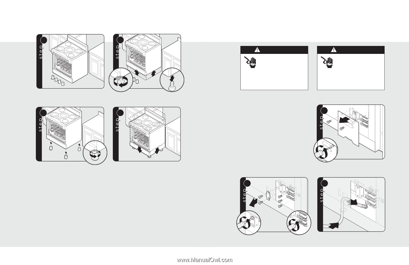
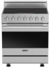
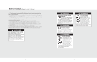
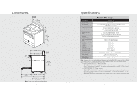
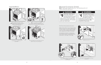
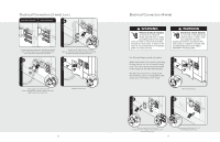
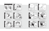
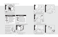
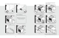
Leg Installation 1 2 Legs are packed in styrofoam top pack. Note: Legs should be installed near to where appliance is to be used, as they are not secure for long transit. 3 1 1 3 2 Note: It is strongly recommended that a pallet or lift jack be used rather than tilting. Raise unit about a foot. Unscrew temporary legs from couplings. 4 Screw legs into couplings on all four corners. Lower range gently to keep any undue strain from legs and internal mounting hardware. 14 Electrical Connection (3-wire) Note: If you have a 4-wire connection, see following section for 4-wire connection instructions. WARNING Electrical shock hazard. To avoid risk or electrical shock, personal injury or death; grounding product to the frame of the unit may or may not be permitted through your local codes. If ground to the frame is not permitted then a 4 conductor power cord must be used. WARNING Electrical shock hazard. To avoid risk of electrical shock, personal injury or death; verify your appliance has been properly grounded in accordance with local codes or in absence of codes, with the National Electrical Code (NEC). ANSI/NFPA 70-latest edition. See Electrical Requirements information. Where local codes do not permit grounding through neutral, use a 4-wire power supply cord. The cord or conduit must be secured to the range with the strain relief bracket. The electrical connection is made at the terminal block, which is located behind the access door on the back of the range. 1 2 1 Remove access door. 2 3 3 1 2 Remove supply cord strain relief bracket and three supply cord mounting screws on terminal block. 15 Feed supply cord up through hole in bottom of range back.
-
 1
1 -
2
-
 3
3 -
 4
4 -
 5
5 -
 6
6 -
 7
7 -
 8
8 -
 9
9 -
 10
10 -
 11
11 -
 12
12 -
 13
13 -
14
 |
 |