Weider 350 Bench English Manual - Page 7
Attach the Leg Lever 4 to the Front Leg 3 - press
 |
View all Weider 350 Bench manuals
Add to My Manuals
Save this manual to your list of manuals |
Page 7 highlights
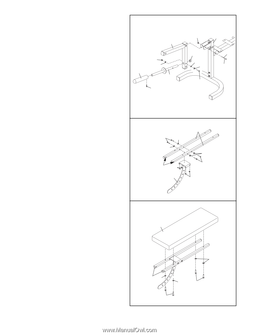
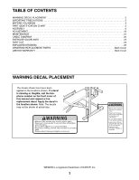
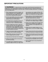
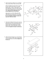
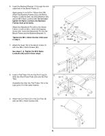
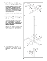
3. Attach the Olympic Adapter (22) to the Weight Tube (6) with an M8 x 10mm Set Screw (99). Attach the Weight Tube (6) inside the Leg Lever (4) with an M8 x 60mm Bolt (91), two M8 Washers (84), a 13mm x 13mm Spacer (78), and an M8 Nylon Locknut (81). Next, press the 25mm Round Angled Cap (19) onto the Weight Tube; make sure the widest part of the Round Angled Cap is at the bottom. Apply grease to an M10 x 68mm Bolt (85). Attach the Leg Lever (4) to the Front Leg (3) with the Bolt and an M10 Nylon Locknut (80). Do not overtighten the Nylon Locknut; the Leg Lever must pivot easily. 3 22 4 81 84 6 99 80 3 19 78 84 85 Grease 91 4. Orient the two Backrest Frames (9) so the indi- 4 cated holes are closer to the bottom. Attach the Backrest Frames to the Backrest Bracket (7) with four M10 x 48mm Bolts (92), four M10 Washers (83), and four M10 Nylon Locknuts (80). Do not tighten the Nylon Locknuts yet. 92 83 83 Holes 80 7 9 83 92 80 5. Attach the Bench Backrest (11) to the Backrest 5 Frames (9) with four M6 x 40mm Screws (100) and four M6 Washers (96). Do not tighten the Screws yet. 11 96 9 96 96 100 100 7
-
 1
1 -
 2
2 -
 3
3 -
 4
4 -
 5
5 -
 6
6 -
 7
7 -
 8
8 -
 9
9 -
 10
10 -
 11
11 -
 12
12 -
13
-
14
-
15
-
16
-
17
-
18
-
19
-
20
-
21
-
22
-
23
-
24
-
25
-
26
-
27
-
28
 |
 |