Weider 9645 Instruction Manual - Page 13
Cable Assembly
 |
View all Weider 9645 manuals
Add to My Manuals
Save this manual to your list of manuals |
Page 13 highlights
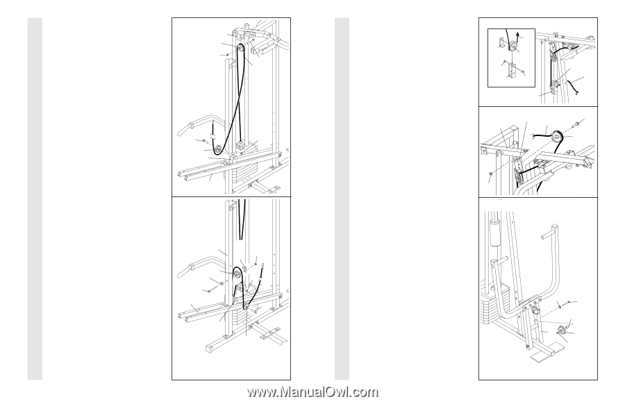
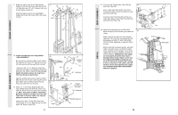
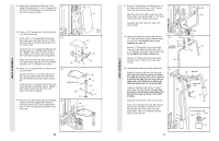
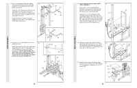
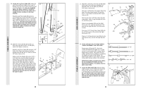
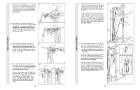
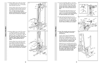
CABLE ASSEMBLY CABLE ASSEMBLY 34. Wrap the Military Press Cable (72) around a 34 "V"-Pulley (50). Attach the "V"-Pulley to the Top Frame (55) with a 3/8" x 2 1/2" Bolt (86) and a 3/8" Nylon Locknut (21). Wrap the Military Press Cable (72) around a 3 1/2" Pulley (15). Attach the Pulley to the indicated bracket on the Assist Arm (105) with a 3/8" x 1 3/4" Bolt (76) and a 3/8" Nylon Locknut (21). Be sure that the Cable is between the Pulley and the Assist Arm and that the Cable and Pulley move smoothly. 55 50 21 86 72 76 21 15 Bracket 35. Wrap the Military Press Cable (72) around a "V"-Pulley (50). Attach the "V"-Pulley and a Long Cable Trap (31) to the Assist Upright (74) with a 3/8" x 4 1/2" Bolt (112), a 3/8" Flat Washer (9), and a 3/8" Nylon Locknut (21). Be sure that the Long Cable Trap is turned to hold the Cable in place and that the Cable is routed around the Pulley as shown. Wrap the Military Press Cable (72) around a 3 1/2" Pulley (15). Attach the Pulley to the other bracket on the Assist Arm (105) with a 3/8" x 1 3/4" Bolt (76) and a 3/8" Nylon Locknut (21). Be sure that the Cable is between the Pulley and the Assist Arm and that the Cable and Pulley move smoothly. 105 35 74 50 9 112 105 Bracket 21 31 21 72 76 15 16 24. See the inset drawing. Attach a 3 1/2" Pulley (15) and a Cable Trap (66) to the upper hole in a Long "U"-Bracket (57) with a 3/8" x 2" Bolt (12) and a 3/8" Nylon Locknut (21). Be sure that the Cable Trap is inside the Long "U"Bracket. Note: This may come pre-assembled. Route the High Cable (58) through the Long "U"-Bracket (57) and the 3 1/2" Pulley (15) shown in the inset drawing. Be sure that the Cable is in the groove of the Pulley and that the Cable and Pulley move smoothly. 25. Wrap the High Cable (58) around a 3 1/2" Pulley (15). Attach the Pulley to the bracket on the Top Frame (55) with a 3/8" x 2" Bolt (12) and a 3/8" Nylon Locknut (21). Be sure that the Cable is in the groove of the Pulley and that the Cable and Pulley move smoothly. 24 66 21 57 25 55 58 15 12 57 Bracket 58 15 58 12 15 21 26. Note: This assembly step shows how to complete the assembly of several pre- 26 attached parts. The 5/8" x 9/16" Spacer (7) has been preattached on the outside of the 3 1/2" Low Pulley (102) for shipping purposes. Remove the 3/8" Nylon Locknut (21), the Spacer, and the Pulley from the 3/8" x 3 3/4" Bolt (88). Do not remove the Bolt. The Bolt has been shown removed for part identification. Reattach the 3 1/2" Low Pulley (102), with the 5/8" x 9/16" Spacer (7) between the Pulley and the Press Frame (17). Do not tighten the 3/8" Nylon Locknut (21) yet. Be sure that the 3/8" x 3 3/4" Bolt (88), the 3/8" Flat Washer (9), the 5/8" x 9/16" Spacer (7), the 3 1/2" Low Pulley (102), and the 3/8" Nylon Locknut (21) are oriented as shown. 13 9 88 7 17 102 21
-
 1
1 -
2
-
3
-
4
-
5
-
6
-
7
-
 8
8 -
 9
9 -
 10
10 -
 11
11 -
 12
12 -
 13
13 -
 14
14 -
 15
15 -
 16
16 -
 17
17 -
 18
18 -
19
 |
 |