Weider 9645 Instruction Manual - Page 14
Locate the Military Press Cable 72.
 |
View all Weider 9645 manuals
Add to My Manuals
Save this manual to your list of manuals |
Page 14 highlights
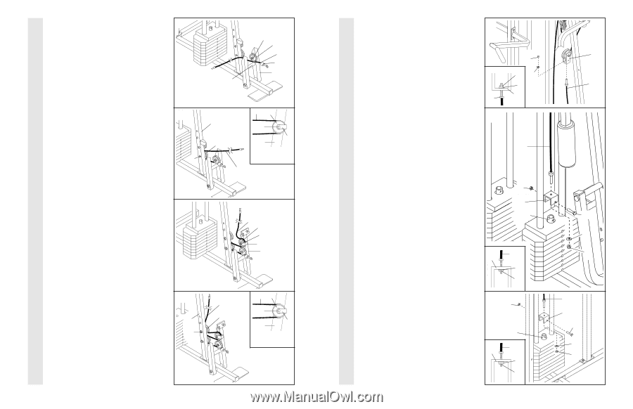
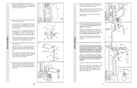
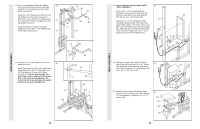
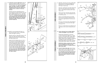
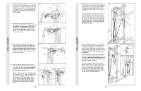
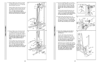
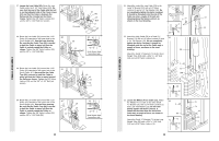
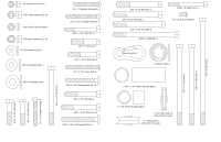
CABLE ASSEMBLY CABLE ASSEMBLY 27. Locate the Low Cable (23). Route the Low 27 Cable under the 3 1/2" Low Pulley (102). Be sure that the end of the Cable with the ball is on the indicated side of the Press Frame (17) and that the Cable is between the Pulley and the crossbar on the Press Frame. Tighten the 3/8" Nylon Locknut (21) and the 3/8" x 3 3/4" Bolt (not shown). Crossbar 21 102 23 Ball 17 28. Route the Low Cable (23) around the 3 1/2" Pulley (15) attached to the lower hole in the Front Upright (42). See the inset drawing. Be sure that the Cable Trap (66) is turned to hold the Cable in place and that the Cable is routed around the Pulley as shown. Tighten the 3/8" Nylon Locknut (21) and the 3/8" x 3 3/4" Bolt (88). 28 21 42 15 23 15 88 66 42 Inset shows view from other side 23 29. Route the Low Cable (23) around the 3 1/2" Pulley (15) attached to the upper hole in the 29 Press Frame (17). Be sure that the Cable Trap (66) is turned to hold the Cable in place and that the Cable is routed around the Pulley as shown. Tighten the 3/8" Nylon Locknut (21) and the 3/8" x 3 1/2" Bolt (not shown). 23 15 21 66 17 30. Route the Low Cable (23) around the 3 1/2" 30 Pulley (15) attached to the upper hole in the Front Upright (42). See the inset drawing. 23 Be sure that the Cable Trap (66) is turned to hold the Cable in place and that the 15 42 Cable is routed around the Pulley as shown. Tighten the 3/8" Nylon Locknut (21) 21 and the 3/8" x 3 3/4" Bolt (88). 23 15 88 66 42 Inset shows view from other side 14 31. Attach the end of the Low Cable (23) to the 31 Long "U"-Bracket (57) with a 1/4" Nylon Locknut (2) and a 1/4" Flat Washer (10). Do not completely tighten the Nylon Locknut. It should be threaded onto the end of the Cable so only a couple of threads are showing above the Nylon Locknut, as shown in the inset drawing. 23 32. Attach the High Cable (58) to a Small "U"Bracket (71) with a 1/4" Nylon Locknut (2) and 32 a 1/4" Flat Washer (10). Do not completely tighten the Nylon Locknut. It should be threaded onto the end of the Cable only a couple of turns, as shown in the inset drawing. Attach the Small "U"-Bracket (71) to the Short Weight Tube (108) with a 5/16" x 1 3/4" Bolt (24) and a 5/16" Nylon Locknut (3). 2 2 10 10 57 58 3 71 108 58 71 10 2 33. Locate the Military Press Cable (72). Attach 33 the Military Press Cable to the other Small "U"-Bracket (71) with a 1/4" Nylon Locknut (2) 3 and a 1/4" Flat Washer (10). Do not com- pletely tighten the Nylon Locknut. It should be threaded onto the end of the Cable only a couple of turns, as shown in 63 the inset drawing. Attach the Small "U"-Bracket (71) to the Long 71 Weight Tube (63) with a 5/16" x 1 3/4" Bolt (24) and a 5/16" Nylon Locknut (3). 72 10 2 15 57 23 24 10 2 72 71 24 10 2
-
 1
1 -
2
-
3
-
4
-
5
-
6
-
7
-
8
-
 9
9 -
 10
10 -
 11
11 -
 12
12 -
 13
13 -
 14
14 -
 15
15 -
 16
16 -
 17
17 -
 18
18 -
 19
19
 |
 |