Weider 9645 Instruction Manual - Page 8
Seat Assembly, Decal, Frame Assembly, Arm Assembly - pro cable diagram
 |
View all Weider 9645 manuals
Add to My Manuals
Save this manual to your list of manuals |
Page 8 highlights
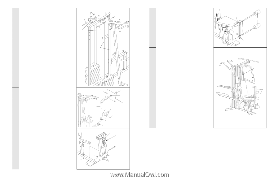
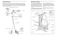
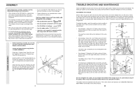
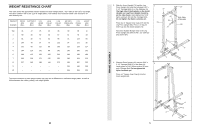
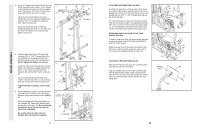
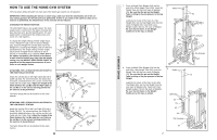
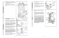
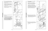
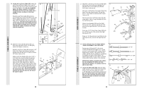
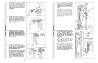
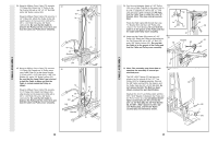
ARM ASSEMBLY FRAME ASSEMBLY 9. Attach the upper ends of the Short Weight Guides (73) to the Top Frame (55) with a 5/16" x 6" Bolt (60), two 1/2" x 3/4" Spacers (61), and a 5/16" Nylon Locknut (3). Attach the upper ends of the Long Weight Guides (62) to the Top Frame (55) in the same manner. 9 61 60 73 3 61 60 3 55 62 10. Locate and open the parts bag labelled "ARM ASSEMBLY." 10 Be sure there is a Bushing (98) in each side of the Stabiliser (5). Press a 2" Square Inner Cap (27) into each end of the Leg Press Arm (96). Lubricate a 3/8" x 3 1/4" Bolt (67). Attach the Leg Press Arm (96) to the Stabiliser (5) with the Bolt and a 3/8" Nylon Locknut (21). Do not overtighten the Nylon Locknut. The Leg Press Arm must be able to pivot freely. Align the welded tubes on the Leg Press Plate (95) with one set of holes in the Leg Press Arm (96). Attach the Leg Press Plate to the Leg 11 Press Arm with the Press Pin (97). 11. Press a 1" x 7/8" Plastic Bushing (90) onto each welded spacer on the Press Frame (17). Slide the Press Frame into place onto the Base (4). Note: This will be a tight fit. The Plastic Bushings should fit on each end of the indicated tube in the Base. Make sure that the pulleys are on the side shown. Lubricate the 3/8" x 8" Bolt (59). Attach the Press Frame (17) to the Base (4) with the Bolt and a 3/8" Nylon Locknut (21). 4 Tube 8 95 27 Welded Tube 97 96 21 27 67-Lubricate 5 27 98 17 Pulleys must be on this side 59-Lubricate 21 Welded Spacers 90 DECAL SEAT ASSEMBLY 47. Press two 3/4" Round Inner Caps (34) into 47 each Pad Tube (28). Insert a Pad Tube (28) into the Front Seat Frame (36). Slide a Foam Pad (30) onto each end of the Pad Tube. Insert the other Pad Tube (28) into the Leg Lever (29). Slide a Foam Foam Pad (30) onto each end of the Pad Tube. 48. Remove the backing from the PRO 9645 48 decal and apply it to the home gym system as shown. Make sure that all parts have been properly tightened. The use of the remaining parts will be explained in HOW TO USE THE HOME GYM SYSTEM, beginning on page 22 of this manual. Before using the home gym system, pull each cable a few times to be sure that the cables move smoothly over the pulleys. If one of the cables does not move smoothly, find and correct the problem. IMPORTANT: If the cables are not properly installed, they may be damaged when heavy weight is used. See the CABLE DIAGRAMS on pages 26 and 27 of this manual for proper cable routing. If there is any slack in the cables, you will need to remove it by tightening the cables. See TROUBLE-SHOOTING AND MAINTENANCE on page 25. 36 30 34 28 34 30 29 PRO 9645 21
-
 1
1 -
2
-
 3
3 -
 4
4 -
 5
5 -
 6
6 -
 7
7 -
 8
8 -
 9
9 -
 10
10 -
 11
11 -
 12
12 -
 13
13 -
14
-
15
-
16
-
17
-
18
-
19
 |
 |