Weider 9645 Instruction Manual - Page 4
Trouble-shooting And Maintenance, Assembly
 |
View all Weider 9645 manuals
Add to My Manuals
Save this manual to your list of manuals |
Page 4 highlights
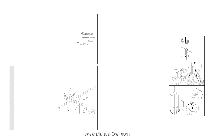
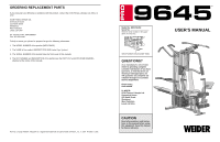
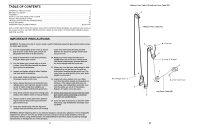
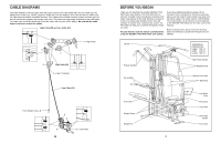
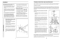
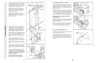
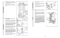
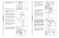
ASSEMBLY Before beginning assembly, carefully read the following information and instructions: • Place all parts of the PRO 9645 in a cleared area and remove the packing materials; do not dispose of the packing materials until assembly is completed. • The assembly is broken into four stages: 1) frame assembly, 2) arm assembly, 3) cable and pulley assembly, and 4) seat and backrest assembly. The hardware for each stage is packaged separately. • Wait until you begin each assembly stage to open the parts bag labelled for that assembly stage. • For help identifying the small parts used in assembly, use the PART IDENTIFICATION CHART located in the centre of this manual. Note: Some small parts may have been preattached for shipping. If a part is not in the parts bag, check to see if it has been pre-attached. • As you assemble the PRO 9645 be sure that all parts are oriented as shown in the drawings. • Tighten all parts as you assemble them, unless instructed to do otherwise. THE FOLLOWING TOOLS (NOT INCLUDED) ARE REQUIRED FOR ASSEMBLY: • Two (2) adjustable spanners • One (1) standard screwdriver • One (1) phillips screwdriver • One (1) rubber mallet • Lubricant, such as grease or petroleum jelly, and soapy water will also be needed. Assembly will be more convenient if you have the following tools: A socket set, a set of open-end or closed-end wrenches, or a set of ratchet wrenches. FRAME ASSEMBLY 1. Before beginning assembly, be sure that you have read and understand the information in the box above. Locate and open the parts bag labelled "FRAME ASSEMBLY." Press two 2" Square Outer Caps (51) onto the Stabiliser (5). Press a 2" Square Inner Cap (27) into the Base (4). Insert six 5/16" x 2 1/2" Carriage Bolts (1) up through the Stabiliser (5). Insert two 5/16" x 2 1/2" Carriage Bolts up through the Base (4). Attach the Base (4) to the Stabiliser (5) with two 5/16" x 2 3/4" Bolts (11), two 5/16" Flat Washers (8), and two 5/16" Nylon Locknuts (3). Do not tighten the Nylon Locknuts yet. 1 51 51 11 8 5 1 1 3 41 27 4 TROUBLE-SHOOTING AND MAINTENANCE Inspect and tighten all parts each time you use the home gym system. Replace any worn parts immediately. The home gym system can be cleaned using a damp cloth and mild non-abrasive detergent. Do not use solvents. TIGHTENING THE CABLES Woven cable, the type of cable used on the home gym system, can stretch slightly when it is first used. If there is slack in the cables before resistance is felt, the cables should be tightened. If any slack is felt when using the front weight stack, both the High Cable (58) and the Low Cable (23) will need to be tightened. If any slack is felt when using the rear weight stack, both the Military Press Cable (72) and the Leg Press Cable (99) will need to be tightened. To tighten the cables, insert the weight pin into the middle of the weight stack. Slack can be removed from these cables several ways: • See drawing 1. Tighten the 1/4" Nylon Locknut (2) that connects the end of the Low Cable (23) to the Long "U"Bracket (57). The Leg Press Cable (99) can be tightened in the same manner. • See drawing 1. Move the 3 1/2" Pulley (15) to the other hole in one of the Long "U"-Brackets (57). Remove the 3/8" Nylon Locknut (21) and the 3/8" x 2" Bolt (12) from the Cable Trap (66), Pulley, and Long "U"-Bracket. Reattach the Pulley and Cable Trap. Be sure that the Cable Trap is in the proper position and that the Cable and Pulley move smoothly. The other Long "U"-Bracket (57) can be adjusted in the same manner. • See drawing 2. Tighten the 1/4" Nylon Locknut (2) that connects the end of the High Cable (58) to the Small "U"Bracket (71). 1 66 21 57 15 12 2 2 72 71 2 58 71 23 or 99 2 3 The Military Press Cable (72) can be tightened in the same manner. • See Drawing 3. If additional slack is felt while using the Leg Press Arm (96), then the end of the Leg Press Cable (99) must be moved to the next hole in the Rear Seat Frame (100). Remove the 5/16" x 2 3/4" Bolt (11), the 5/16" Washer (8), the end of the Cable, and both 5/16" Nylon Jam Nuts (93) from the Rear Seat Frame. Reattach the Bolt, the Washer, the end of the Cable, and both Nylon Jam Nuts to the next hole in the Rear Seat Frame. 96 11 8 100 99 93 93 Do not overtighten the cables; the top weight will be lifted off the weight stack. If a cable tends to slip off the pulleys often, it may have become twisted. Remove the cable and re-install it. The cables need to be replaced evey two years. If the cables need to be replaced, see ORDERING REPLACEMENT PARTS on the back cover of this manual. 25
-
 1
1 -
 2
2 -
 3
3 -
 4
4 -
 5
5 -
 6
6 -
 7
7 -
 8
8 -
 9
9 -
 10
10 -
11
-
12
-
13
-
14
-
15
-
16
-
17
-
18
-
19
 |
 |