Weider 9645 Instruction Manual - Page 17
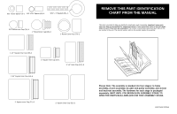
Remove This Part List/exploded, Drawing Chart From The Manual
 |
View all Weider 9645 manuals
Add to My Manuals
Save this manual to your list of manuals |
Page 17 highlights
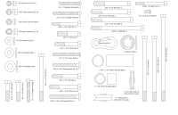
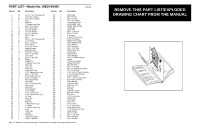
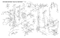
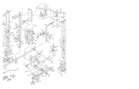
PART LIST-Model No. WESY96450 R0996A Key No. Qty. 1 10 2 6 3 36 4 1 5 1 6 1 7 1 8 9 9 9 10 15 11 14 12 5 13 2 14 1 15 13 16 1 17 1 18 6 19 4 20 1 21 23 22 4 23 1 24 2 25 18 26 2 27 8 28 2 29 1 30 4 31 4 32 4 33 3 34 4 35 1 36 1 37 2 38 1 39 1 40 1 41 1 42 1 43 8 44 6 45 2 46 2 47 1 48 1 49 6 50 5 51 2 52 1 53 3 54 1 55 1 56 1 57 2 Description 5/16" x 2 1/2" Carriage Bolt 1/4" Nylon Locknut 5/16" Nylon Locknut Base Stabiliser 1" Square Inner Cap 5/8" x 9/16" Spacer 5/16" Flat Washer 3/8" Flat Washer 1/4" Flat Washer 5/16" x 2 3/4" Bolt 3/8" x 2" Bolt Seat 5/16" x 2 3/4" Carriage Bolt 3 1/2" Pulley 3/8" x 3 1/2" Bolt Press Frame 1/4" x 1/2" Screw Weight Bumper Pulley Bracket 3/8" Nylon Locknut 5/16" x 2 1/2" Bolt Low Cable 5/16" x 1 3/4" Bolt Weight Weight Pin 2" Square Inner Cap Pad Tube Leg Lever Foam Pad Long Cable Trap 1 1/2" Square Inner Cap 5/16" x 2 1/4" Bolt 3/4" Round Inner Cap 5/16" x 2" Eyebolt Front Seat Frame Seat Plate 1/4" x 2" Carriage Bolt Nylon Strap Seat Knob Front Backrest Front Upright 1/4" x 2 1/2" Screw 1 3/4" Square Inner Cap 10" Pad Press Arm Left Arm Right Arm 1" Round Inner Cap "V"-Pulley 2" Square Outer Cap Chain Cable Clip Lat Bar Top Frame Leg Press Upright Long "U"-Bracket Key No. Qty. 58 1 59 1 60 2 61 4 62 2 63 1 64 2 65 2 66 7 67 2 68 1 69 4 70 2 71 2 72 1 73 2 74 1 75 1 76 2 77 1 78 1 79 1 80 2 81 1 82 1 83 8 84 1 85 1 86 4 87 1 88 6 89 2 90 2 91 1 92 1 93 4 94 1 95 1 96 1 97 1 98 2 99 1 100 1 101 1 102 1 103 2 104 1 105 1 106 1 107 2 108 1 109 6 110 1 111 1 112 1 113 2 # 1 Description High Cable 3/8" x 8" Bolt 5/16" x 6" Bolt 1/2" x 3/4" Spacer Long Weight Guide Long Weight Tube Weight Tube Bumper Top Weight Cable Trap 3/8" x 3 1/4" Bolt 5/16" x 5" Bolt 1" Retainer 1" Round Cover Cap Small "U"-Bracket Military Press Cable Short Weight Guide Assist Upright Left Pull-up Arm 3/8" x 1 3/4" Bolt Right Pull-up Arm Left Dip Arm Right Dip Arm Long Handgrip 1/4" x 2" Machine Screw Handle 5" Plastic Handgrip Military Press Arm Rear Backrest 3/8" x 2 1/2" Bolt #8 x 1/2" Self-tapping Screw 3/8" x 3 3/4" Bolt 1 1/8" x 2 1/2" Plastic Bushing 1" x 7/8" Plastic Bushing Rubber Bumper 1/4" x 2 1/2" Carriage Bolt 5/16" Nylon Jam Nut Press Bracket Leg Press Plate Leg Press Arm Press Pin Bushing Leg Press Cable Rear Seat Frame Pivot Arm 3 1/2" Low Pulley Handle Cap Assist Seat Assist Arm 3/8" x 6" Bolt 1" x 2" Inner Cap Short Weight Tube 1 1/4" Round Inner Cap Angle Bracket 5/16" x 3" Bolt 3/8" x 4 1/2" Bolt Short Handgrip User's Manual Note: "#" indicates a non-illustrated part. Specifications are subject to change without notice. REMOVE THIS PART LIST/EXPLODED DRAWING CHART FROM THE MANUAL 81
-
 1
1 -
2
-
3
-
4
-
5
-
6
-
7
-
8
-
9
-
10
-
11
-
 12
12 -
 13
13 -
 14
14 -
 15
15 -
 16
16 -
 17
17 -
 18
18 -
 19
19
 |
 |
