Weider 9645 Instruction Manual - Page 9
Seat Assembly, Arm Assembly
 |
View all Weider 9645 manuals
Add to My Manuals
Save this manual to your list of manuals |
Page 9 highlights
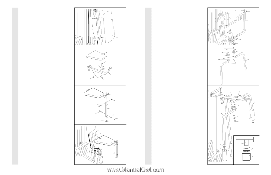
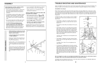
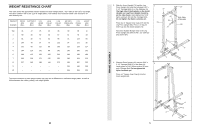
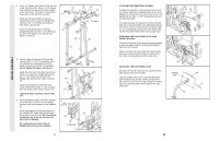
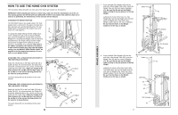
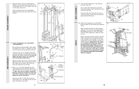
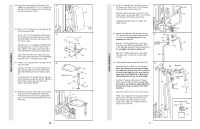
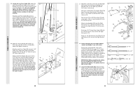
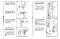
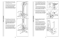
SEAT ASSEMBLY ARM ASSEMBLY 43. Attach the Front Backrest (41) to the Front 43 Upright (42) with two 1/4" x 2 1/2" Screws (43) and two 1/4" Flat Washers (10). The Backrest must be oriented as shown. 42 41 43 10 44. Press a 1 1/2" Square Inner Cap (32) into the Front Seat Frame (36). Insert a 1/4" x 2" Carriage Bolt (38) through the centre hole in the Seat Plate (37). Attach the Seat Plate to the Seat (13) with two 1/4" x 1/2" Screws (18). Insert the 1/4" x 2" Carriage Bolt (38) through the indicated hole in the Front Seat Frame (36). Tighten a 1/4" Nylon Locknut (2) with a 1/4" Flat Washer (10) onto the Carriage Bolt. Attach the other end of the Seat (13) to the Front Seat Frame (36) with a 1/4" Flat Washer (10) and a 1/4" x 2" Machine Screw (81). 45. Press a 1 1/2" Square Inner Cap (32) into the Leg Lever (29). Lubricate the 5/16" x 2 1/4" Bolt (33). Attach the Leg Lever (29) to the Front Seat Frame (36) with the Bolt and a 5/16" Nylon Locknut (3). Insert the 5/16" x 2" Eyebolt (35) into the Leg Lever (29) from the direction shown. Tighten a 5/16" Nylon Locknut (3) with a 5/16" Flat Washer (8) onto the Eyebolt. 46. Rest the Front Seat Frame (36) on the indicated pin in the Front Upright (42). Attach the Front Seat Frame to the Front Upright with a 5/16" x 2 3/4" Carriage Bolt (14) and the Seat Knob (40). Thick End 44 13 38 37 18 32 36 81 10 2 45 Lubricate-33 35 32 46 14 42 40 36 36 3 29 8 3 Pin 20 12. Press a 1" Round Inner Cap (49) into one of 12 the Press Arms (46). Press a 1 3/4" Square Inner Cap (44) into the Press Arm. 44 49 Attach the Press Arm (46) to one side of the 46 Press Frame (17) with two 5/16" x 2 1/2" Bolts (22) and two 5/16" Nylon Locknuts (3). 22 Assemble the other Press Arm (46) in the same manner. 46 3 17 13. Identify the Right Arm (48) and the Left Arm (47). Note the position of the welded bracket on each Arm. Arm identification is very important for step 14. Attach a "V"-Pulley (50) and a Long Cable Trap (31) to the Right Arm (48) with a 3/8" x 2 1/2" Bolt (86) and a 3/8" Nylon Locknut (21). Do not tighten the Nylon Locknut yet. 13 86 31 50 Welded Brackets 31 50 47 21 Attach a "V"-Pulley (50) and a Long Cable Trap (31) to the Left Arm (47) in the same 48 manner. 14. Lubricate both axles on the Top Frame (55). 14 Slide the Right Arm (48) onto the right axle. Note: Be careful not to confuse the Right Arm with the Left Arm (47); refer to step 13 to identify the Right Arm. Be sure that the upper end of the Right Arm is behind the indicated bracket on the Top Frame (55). Tap two 1" Retainers (69) and a 1" Round Cover Cap (70) onto the axle. Be sure that 48 the teeth on the Retainers bend toward the Round Cover Cap, as shown in the inset drawing. Attach the Left Arm (47) in the same manner. Press 1 3/4" Square Inner Caps (44) into the lower ends of the Right and Left Arms (47, 48). Wet the lower end of each Arm with soapy water. Slide a 10" Pad (45) onto the lower end of each Arm. 44 45 55 Bracket 47 Lubricate Axle 69 45 70 44 Axle 69 70 9
-
 1
1 -
2
-
3
-
 4
4 -
 5
5 -
 6
6 -
 7
7 -
 8
8 -
 9
9 -
 10
10 -
 11
11 -
 12
12 -
 13
13 -
 14
14 -
15
-
16
-
17
-
18
-
19
 |
 |