Weider Pro 355 English Manual - Page 10
Adjustment, Backrest, Bracket, oriented, shown.
 |
View all Weider Pro 355 manuals
Add to My Manuals
Save this manual to your list of manuals |
Page 10 highlights
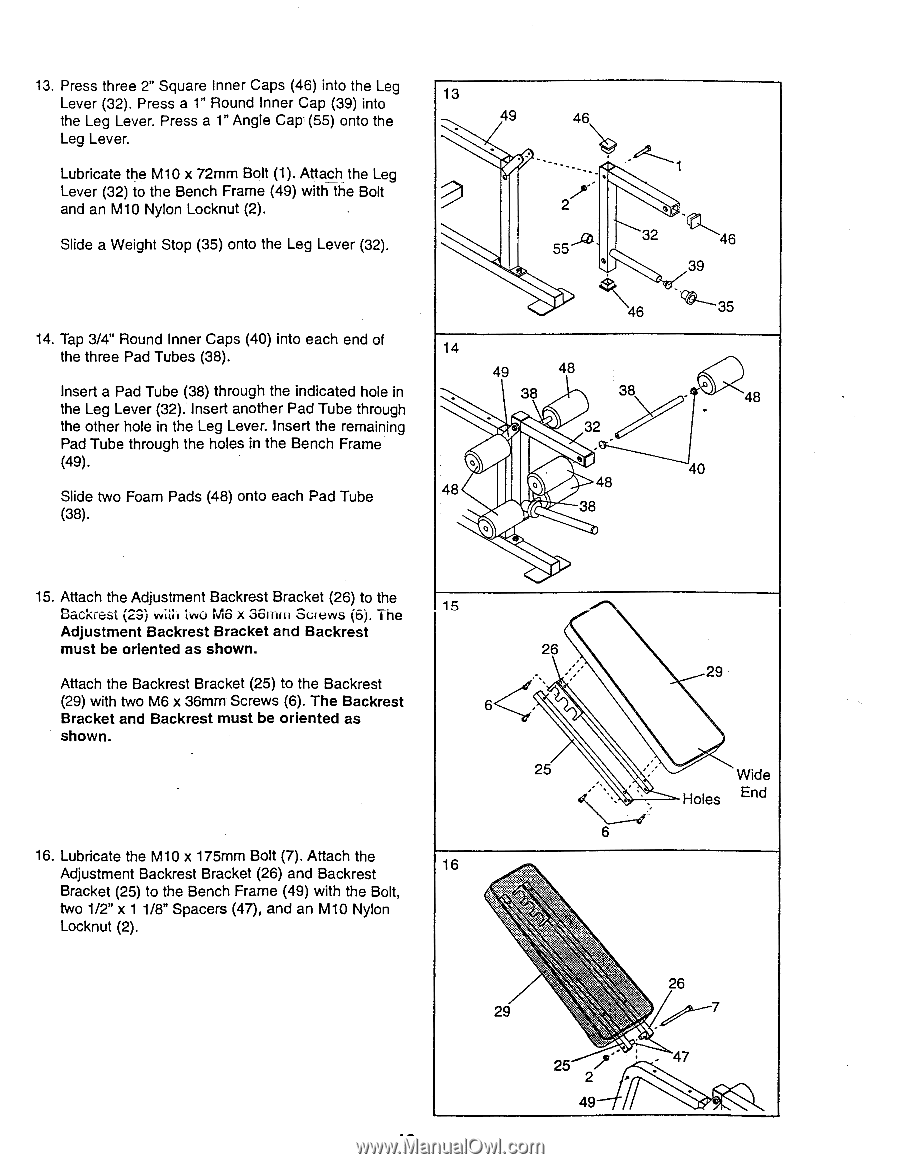
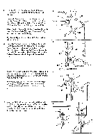
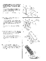
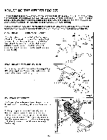
13. Press three 2" Square Inner Caps (46) into the Leg Lever (32). Press a 1" Round Inner Cap (39) into 13 the Leg Lever. Press a 1" Angle Cap' (55) onto the 49 46 Leg Lever. Lubricate the M10 x 72mm Bolt (1). Attach the Leg Lever (32) to the Bench Frame (49) with the Bolt and an M10 Nylon Locknut (2). 2 Slide a Weight Stop (35) onto the Leg Lever (32). 55 32 46 39 14. Tap 3/4" Round Inner Caps (40) into each end of the three Pad Tubes (38). Insert a Pad Tube (38) through the indicated hole in the Leg Lever (32). Insert another Pad Tube through the other hole in the Leg Lever. Insert the remaining Pad Tube through the holes in the Bench Frame (49). Slide two Foam Pads (48) onto each Pad Tube (38). 46 14 49 48 38 38 32 0 48 0 48 38 0 48 40 15. Attach the Adjustment Backrest Bracket (26) to the Backrest (29) with two MG x 36r-cirri Screws (6). The 15 Adjustment Backrest Bracket and Backrest must be oriented as shown. 26 Attach the Backrest Bracket (25) to the Backrest (29) with two M6 x 36mm Screws (6). The Backrest 6 Bracket and Backrest must be oriented as shown. 25 6 16. Lubricate the M10 x 175mm Bolt (7). Attach the Adjustment Backrest Bracket (26) and Backrest 16 Bracket (25) to the Bench Frame (49) with the Bolt, two 1/2" x 1 1/8" Spacers (47), and an M10 Nylon Locknut (2). 29 Wide Holes End 29 25 , 2 49 26 . 47
-
 1
1 -
2
-
3
-
4
-
 5
5 -
 6
6 -
 7
7 -
 8
8 -
 9
9 -
 10
10 -
 11
11 -
 12
12 -
 13
13 -
 14
14 -
 15
15 -
16
-
17
-
18
-
19
-
20
 |
 |