Xerox 1235N Service Guide - Page 10
_Contents1235.pdf
 |
UPC - 042215474580
View all Xerox 1235N manuals
Add to My Manuals
Save this manual to your list of manuals |
Page 10 highlights
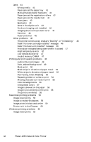
Figures The Phaser 1235 Color Printer with lower tray feeders 1 Print engine circuit boards 5 Print engine circuit boards (cont'd) 6 Print engine sensor and switch locations 7 Print engine sensor and switch locations (cont'd) 8 Print engine motors, clutches and solenoids 9 Optional feeder motor and clutch 10 Features of the controller board 11 The control panel 12 The printer rear panel 13 Tray switch sensors and actuators 15 Door safety interlock switches 37 LED Head Test Pattern 68 Print problem caused by dirty LED lens 83 Removing the top cover 87 Removing the left-side cover 88 Removing the right-side cover 89 Removing the rear cover 90 Removing the front cover 91 Removing the face-up tray 92 Removing the right shield plate 93 Removing the electrical chassis 95 Removing the electrical chassis cooling fan 96 Disconnecting the registration motor in-line connector (HOPFF) 97 Removing the printer unit chassis 98 Removing the main cooling fan 99 Removing the top shield plate 100 Removing the harnesses from the electrical chassis 101 Removing the top cover inner frame 102 Removing the left/right top cover spring assembly 103 Removing the lower plate assembly 104 Removing the left paper tray guide assembly 105 Removing the paper tray guide assemblies 106 Removing the right paper tray guide assembly 107 Removing the left plate assembly 108 Removing the system controller board 109 Removing the print engine controller 110 Disconnecting the LED power harnesses 111 Removing the toner sensor board 112 x Phaser 1235 Network Color Printer
-
 1
1 -
2
-
3
-
4
-
 5
5 -
 6
6 -
 7
7 -
 8
8 -
 9
9 -
 10
10 -
 11
11 -
 12
12 -
 13
13 -
 14
14 -
 15
15 -
16
-
17
-
18
-
19
-
20
-
21
-
22
-
23
-
24
-
25
-
26
-
27
-
28
-
29
-
30
-
31
-
32
-
33
-
34
-
35
-
36
-
37
-
38
-
39
-
40
-
41
-
42
-
43
-
44
-
45
-
46
-
47
-
48
-
49
-
50
-
51
-
52
-
53
-
54
-
55
-
56
-
57
-
58
-
59
-
60
-
61
-
62
-
63
-
64
-
65
-
66
-
67
-
68
-
69
-
70
-
71
-
72
-
73
-
74
-
75
-
76
-
77
-
78
-
79
-
80
-
81
-
82
-
83
-
84
-
85
-
86
-
87
-
88
-
89
-
90
-
91
-
92
-
93
-
94
-
95
-
96
-
97
-
98
-
99
-
100
-
101
-
102
-
103
-
104
-
105
-
106
-
107
-
108
-
109
-
110
-
111
-
112
-
113
-
114
-
115
-
116
-
117
-
118
-
119
-
120
-
121
-
122
-
123
-
124
-
125
-
126
-
127
-
128
-
129
-
130
-
131
-
132
-
133
-
134
-
135
-
136
-
137
-
138
-
139
-
140
-
141
-
142
-
143
-
144
-
145
-
146
-
147
-
148
-
149
-
150
-
151
-
152
-
153
-
154
-
155
-
156
-
157
-
158
-
159
-
160
-
161
-
162
-
163
-
164
-
165
-
166
-
167
-
168
-
169
-
170
-
171
-
172
-
173
-
174
-
175
-
176
-
177
-
178
-
179
-
180
-
181
-
182
-
183
-
184
-
185
-
186
-
187
-
188
-
189
-
190
-
191
-
192
-
193
-
194
-
195
-
196
-
197
-
198
-
199
-
200
-
201
-
202
-
203
-
204
-
205
-
206
-
207
-
208
-
209
-
210
-
211
-
212
-
213
-
214
-
215
-
216
-
217
-
218
-
219
-
220
-
221
-
222
-
223
-
224
-
225
-
226
-
227
-
228
-
229
-
230
-
231
-
232
-
233
-
234
-
235
-
236
-
237
-
238
-
239
-
240
 |
 |
