Yamaha SW1000XG SW1000XG Owners Manual - Page 12
Installing the Plug-In Board, Installing the Digital Mixing Card
 |
View all Yamaha SW1000XG manuals
Add to My Manuals
Save this manual to your list of manuals |
Page 12 highlights
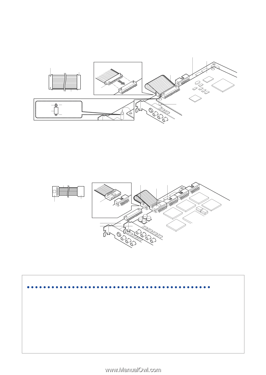
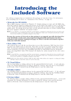
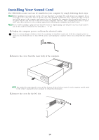
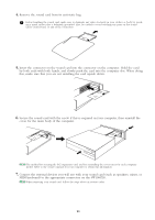
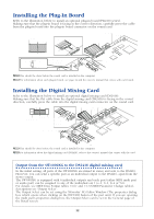
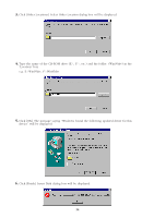
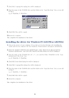
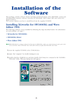
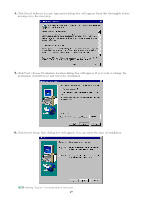
Installing the Plug-In Board Refer to the illustration below to install an optional plug-in board (PLG100 series). Making sure that the plug-in board is facing in the correct direction, carefully press the cable from the plug-in board into the plug-in board connector on the sound card. Connector to SW1000XG Connector to plug-in board Make sure that the flat cable is facing in the correct direction. SW1000XG sound card Plug-in board Yellow line Hooks Spacer Yellow line Flat cable's connector To plug-in board First, put the four spacers in the SW1000XG, then fit the plug-in board above the sound card. To SW1000XG Spacer n This should be done before the sound card is installed in the computer. n For information about each plug-in board, see page 24 and the owner's manual that comes with each board. Installing the Digital Mixing Card Refer to the illustration below to install an optional digital mixing card (DS2416). Making sure that the flat cable from the digital mixing card (DS2416) is facing in the correct direction, carefully press the cable into the digital mixing card connector on the sound card. Green line Green line Serial out Connector Serial In Connector Connector to DS2416 Connector to SW1000XG Make sure that the flat cable from the DS2416 is facing in the correct direction. SW1000XG sound card DS2416 n This should be done before the sound card is installed in the computer. n For information about the digital mixing card (DS2416), refer to the owner's manual that comes with the card. Output from the SW1000XG to the DS2416 digital mixing card In the initial setting, all parts of the SW1000XG are mixed in stereo and sent to the DS2416. However, you can send a specific part as an individual output to the DS2416, apart from the stereo output. The SW1000XG is equipped with 6 individual outputs and each part (either MIDI multi part or audio part) can be assigned to any of the individual out 1 to 6, 1+2, 3+4 or 5+6. For details, see MIDI Data Format tables and (MIDI Parameter Change tables), descriptions on "Output Select". The Output Select can be set using the XGworks' XG Editor Window (The properties dialog box which opens when clicking on the [DETAIL] button of the part unit). If you are opening the multi part's properties dialog box, the Output Select can be set in the General page of the Detail screen. 12
-
 1
1 -
2
-
3
-
4
-
5
-
6
-
 7
7 -
 8
8 -
 9
9 -
 10
10 -
 11
11 -
 12
12 -
 13
13 -
 14
14 -
 15
15 -
 16
16 -
 17
17 -
18
-
19
-
20
-
21
-
22
-
23
-
24
-
25
-
26
-
27
-
28
-
29
-
30
-
31
-
32
-
33
-
34
-
35
-
36
-
37
-
38
-
39
-
40
-
41
-
42
-
43
-
44
-
45
-
46
-
47
-
48
 |
 |