ZyXEL VES1724-56B2 User Guide - Page 107
Table 34, Label, Description
 |
View all ZyXEL VES1724-56B2 manuals
Add to My Manuals
Save this manual to your list of manuals |
Page 107 highlights
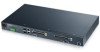
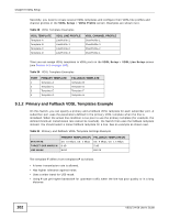
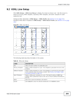
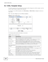
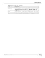
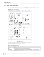
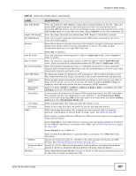
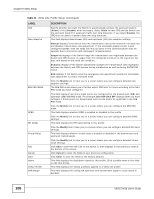
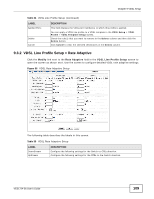
Chapter 9 VDSL Setup Table 34 VDSL Line Profile Setup (continued) LABEL Max SNR Margin Target SNR Margin Min SNR Margin Bitswap Max Rx Power Max Tx Power Min Overhead Rate Limit PSD Mask Transmission Mode ADSL/VDSL Protocol Class Mask Limit Mask US0 Mask UPBO UPBOKL UpStream Band 1 ~ 4 PM Mode DESCRIPTION Enter the maximum SNR (Signal to Noise Ratio) margin allowed on the line. When the actual SNR margin is going to reach this specified value, this mechanism forces connected CPE device(s) to lower its transmission power level and maintains the actual SNR margin equal to or less than this value. Select noLimit to turn this mechanism off. Enter the target upstream and downstream SNR (Signal to Noise Ratio) margin. Enter the minimum upstream and downstream SNR margin accepted on the line to which this profile applies. Select On to allow on-line bits and power (for example, margin) reallocation among the allowed sub-carriers without service interruption or errors. This helps to keep transmission data rate on a high SNR VDSL line. Select Off to disable it. Enter the maximum receiving power in dBm for UpStream traffic. Select noLimit if there is no limit. Enter the maximum transmission power in dBm the Switch uses for DownStream traffic. Enter the maximum transmission power the CPE uses for UpStream traffic. Enter the minimum transmission rate (4~248 kbps) reserved for a line's overhead channel. Both the Switch and CPE device use the overhead channel of a line to get VDSL transmission statistics with each other. To reduce the impact of interference and attenuation, ITU-T G.993.2 specifies a limit PSD mask that limits the VDSL2 transmitters PSD at both downstream and upstream. Select an appropriate transmission standard (according to your territory) you want to apply for this profile. At the time of writing, the Switch supports G.993.2 Annex A mode for countries which follow the North American VDSL2 standard. Select the ADSL (G.992.1, G.992.2, G.992.3, G.992.5, ANSI, and ETSI) and VDSL (G.993.2) protocols this profile uses. A class mask is a combination of several PSD masks according to the PSD mask types. The available options vary depending on your selection in the Transmission Mode field. At the time of writing, 998 is the only option in this field when you select G.993.2 Annex A in the Transmission Mode field. Select a downstream limit mask you want the Switch to use. Select a limit mask you want the Switch to use for the upstream band 0. UPBO (Upstream Power Back-Off) mitigates far-end crosstalk (FEXT) caused by upstream transmission on shorter loops to longer loops. See UPBO on page 98. Select Auto to enable UPBO and CPE devices' PSD adjustment based on the negotiation result with the Switch. Select Override to force CPE devices to use the electrical length defined by the Switch (in the UPBOKL field below) to compute their UPBO. See UPBO/DPBO Electrical Length on page 100. Select Disable to turn UPBO off. Enter variable A and B values of upstream band 1 and band 2 for UPBO PSD mask calculation. Specify the electrical length (0~128 dB) of the cable between the Switch and CPE devices. See UPBO/DPBO Electrical Length on page 100. Specify 40~80.95 (dBm/Hz) for parameter A which defines the original band shape. Specify 0~40.95 for parameter B which defines the power back-off degree. Select allowTransitionsToIdle to have the Switch or CPE devices autonomously enter an idle state for power management (PM). VES1724-56 User's Guide 107
-
 1
1 -
2
-
3
-
4
-
5
-
6
-
7
-
8
-
9
-
10
-
11
-
12
-
13
-
14
-
15
-
16
-
17
-
18
-
19
-
20
-
21
-
22
-
23
-
24
-
25
-
26
-
27
-
28
-
29
-
30
-
31
-
32
-
33
-
34
-
35
-
36
-
37
-
38
-
39
-
40
-
41
-
42
-
43
-
44
-
45
-
46
-
47
-
48
-
49
-
50
-
51
-
52
-
53
-
54
-
55
-
56
-
57
-
58
-
59
-
60
-
61
-
62
-
63
-
64
-
65
-
66
-
67
-
68
-
69
-
70
-
71
-
72
-
73
-
74
-
75
-
76
-
77
-
78
-
79
-
80
-
81
-
82
-
83
-
84
-
85
-
86
-
87
-
88
-
89
-
90
-
91
-
92
-
93
-
94
-
95
-
96
-
97
-
98
-
99
-
100
-
101
-
 102
102 -
 103
103 -
 104
104 -
 105
105 -
 106
106 -
 107
107 -
 108
108 -
 109
109 -
 110
110 -
 111
111 -
 112
112 -
113
-
114
-
115
-
116
-
117
-
118
-
119
-
120
-
121
-
122
-
123
-
124
-
125
-
126
-
127
-
128
-
129
-
130
-
131
-
132
-
133
-
134
-
135
-
136
-
137
-
138
-
139
-
140
-
141
-
142
-
143
-
144
-
145
-
146
-
147
-
148
-
149
-
150
-
151
-
152
-
153
-
154
-
155
-
156
-
157
-
158
-
159
-
160
-
161
-
162
-
163
-
164
-
165
-
166
-
167
-
168
-
169
-
170
-
171
-
172
-
173
-
174
-
175
-
176
-
177
-
178
-
179
-
180
-
181
-
182
-
183
-
184
-
185
-
186
-
187
-
188
-
189
-
190
-
191
-
192
-
193
-
194
-
195
-
196
-
197
-
198
-
199
-
200
-
201
-
202
-
203
-
204
-
205
-
206
-
207
-
208
-
209
-
210
-
211
-
212
-
213
-
214
-
215
-
216
-
217
-
218
-
219
-
220
-
221
-
222
-
223
-
224
-
225
-
226
-
227
-
228
-
229
-
230
-
231
-
232
-
233
-
234
-
235
-
236
-
237
-
238
-
239
-
240
-
241
-
242
-
243
-
244
-
245
-
246
-
247
-
248
-
249
-
250
-
251
-
252
-
253
-
254
-
255
-
256
-
257
-
258
-
259
-
260
-
261
-
262
-
263
-
264
-
265
-
266
-
267
-
268
-
269
-
270
-
271
-
272
-
273
-
274
-
275
-
276
-
277
-
278
-
279
-
280
-
281
-
282
-
283
-
284
-
285
-
286
-
287
-
288
-
289
-
290
-
291
-
292
-
293
-
294
-
295
-
296
-
297
-
298
-
299
-
300
-
301
-
302
-
303
-
304
-
305
-
306
-
307
-
308
-
309
-
310
-
311
-
312
-
313
-
314
-
315
-
316
-
317
-
318
-
319
-
320
-
321
-
322
-
323
-
324
-
325
-
326
-
327
-
328
-
329
-
330
-
331
-
332
-
333
-
334
-
335
-
336
-
337
-
338
-
339
-
340
-
341
-
342
-
343
-
344
-
345
-
346
-
347
-
348
-
349
-
350
-
351
-
352
-
353
-
354
-
355
-
356
-
357
-
358
-
359
-
360
-
361
-
362
-
363
-
364
-
365
-
366
-
367
-
368
-
369
-
370
-
371
-
372
-
373
-
374
-
375
-
376
-
377
-
378
-
379
-
380
-
381
-
382
-
383
-
384
-
385
-
386
-
387
-
388
-
389
-
390
-
391
-
392
-
393
-
394
-
395
-
396
-
397
-
398
-
399
-
400
-
401
-
402
-
403
-
404
-
405
-
406
-
407
-
408
-
409
-
410
-
411
-
412
-
413
-
414
 |
 |
