ZyXEL VES1724-56B2 User Guide - Page 110
Table 35, Label, Description
 |
View all ZyXEL VES1724-56B2 manuals
Add to My Manuals
Save this manual to your list of manuals |
Page 110 highlights
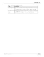
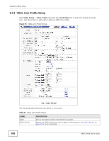
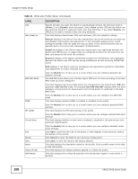
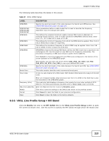
Chapter 9 VDSL Setup Table 35 VDSL Rate Adaptive Setup (continued) LABEL DESCRIPTION Rate Adaptive Select the rate adaptive modes for downstream and upstream transmissions. Select Manual to fix the transmit rate as the minimum net data rate and disable transmission rate adjustment. If the attainable speeds cannot match configured speeds, then the VDSL link may go down or link communications may be sporadic due to line errors and consequent retransmissions. Select AdaptInit to keep the transmit rate negotiated between CO and CPE devices. It ranges from the configured minimum to the maximum net data rate based on the initial line condition. Select Dynamic to dynamically change the transmission rate negotiated between the Switch and CPE devices during initialization as well as during SHOWTIME status. Select SOS to use the emergency rate adjustment system for immediate rate adjustment to reduce crosstalk noise. DynamicDepth Select Enable to allow the Switch to dynamically change interleaving depth for downstream or upstream traffic. In addition, this enables the Switch to change the lower and upper boundaries of the net data rate and improve the ability of SRA (Seamless Rate Adaptation). Alternatively, select Diable to have the Switch use a fixed interleaving depth. Up-Shift SNR Margin Enter the number of decibels (dB) for the line's up-shift SNR margin threshold. When the line's signal-to-noise margin goes above this number, the Switch attempts to use a higher transmission rate. Up-Shift Time Enter the number of seconds the Switch has to wait before using a higher transmission rate when the line's SNR margin is over the up-shift SNR margin threshold. Down-Shift SNR Margin Enter the number of decibels (dB) for the line's down-shift SNR margin threshold. When the line's signal-to-noise margin goes below this number, the Switch attempts to use a lower transmission rate. Down-Shift Time Enter the number of seconds the Switch waits before using a lower transmission rate when the line's SNR margin is less the down-shift SNR margin threshold. Modify Click this to save the settings to the Switch and return to the previous screen. SOS Time Specify the time interval (from 64 to 16320) at which the Switch initiates an SOS request. SOS CRC Specify the maximum number of CRC errors which are allowed during the specified SOS time interval before the Switch initiates an SOS request. SOS nTones Specify the maximum percentage (from 0 to 100) of persistently degraded tones in the MEDLEY set which are allowed during the specified SOS time interval before the Switch initiates an SOS request. SOS Max Specify the maximum number (from 0 to 15) of successful SOS processes which are allowed within 120 seconds before the Switch goes to the L3 link state. An SOS process is considered successful when the Switch receives a synchronous signal (SyncFlag). SOS Multi-Step Tones Select to adjust bits for all tones in an SOS request. ROC enable A ROC (robust overhead channel) is a latency path that carries only overhead data. ROC SNR Margin ROC min INP Select Enable to use a ROC to transmit SOS information to ensure that the message can be received correctly. Otherwise, select Disable. Specify the (Signal to Noise Ratio) margin allowed for a robust overhead channel. When the actual SNR margin is going to reach this specified value, a robust overhead channel is negotiated for reliable transmission. Specify the level of impulse noise (burst) protection for a robust overhead channel. Select a number between 0 and 16. 110 VES1724-56 User's Guide
-
 1
1 -
2
-
3
-
4
-
5
-
6
-
7
-
8
-
9
-
10
-
11
-
12
-
13
-
14
-
15
-
16
-
17
-
18
-
19
-
20
-
21
-
22
-
23
-
24
-
25
-
26
-
27
-
28
-
29
-
30
-
31
-
32
-
33
-
34
-
35
-
36
-
37
-
38
-
39
-
40
-
41
-
42
-
43
-
44
-
45
-
46
-
47
-
48
-
49
-
50
-
51
-
52
-
53
-
54
-
55
-
56
-
57
-
58
-
59
-
60
-
61
-
62
-
63
-
64
-
65
-
66
-
67
-
68
-
69
-
70
-
71
-
72
-
73
-
74
-
75
-
76
-
77
-
78
-
79
-
80
-
81
-
82
-
83
-
84
-
85
-
86
-
87
-
88
-
89
-
90
-
91
-
92
-
93
-
94
-
95
-
96
-
97
-
98
-
99
-
100
-
101
-
102
-
103
-
104
-
 105
105 -
 106
106 -
 107
107 -
 108
108 -
 109
109 -
 110
110 -
 111
111 -
 112
112 -
 113
113 -
 114
114 -
 115
115 -
116
-
117
-
118
-
119
-
120
-
121
-
122
-
123
-
124
-
125
-
126
-
127
-
128
-
129
-
130
-
131
-
132
-
133
-
134
-
135
-
136
-
137
-
138
-
139
-
140
-
141
-
142
-
143
-
144
-
145
-
146
-
147
-
148
-
149
-
150
-
151
-
152
-
153
-
154
-
155
-
156
-
157
-
158
-
159
-
160
-
161
-
162
-
163
-
164
-
165
-
166
-
167
-
168
-
169
-
170
-
171
-
172
-
173
-
174
-
175
-
176
-
177
-
178
-
179
-
180
-
181
-
182
-
183
-
184
-
185
-
186
-
187
-
188
-
189
-
190
-
191
-
192
-
193
-
194
-
195
-
196
-
197
-
198
-
199
-
200
-
201
-
202
-
203
-
204
-
205
-
206
-
207
-
208
-
209
-
210
-
211
-
212
-
213
-
214
-
215
-
216
-
217
-
218
-
219
-
220
-
221
-
222
-
223
-
224
-
225
-
226
-
227
-
228
-
229
-
230
-
231
-
232
-
233
-
234
-
235
-
236
-
237
-
238
-
239
-
240
-
241
-
242
-
243
-
244
-
245
-
246
-
247
-
248
-
249
-
250
-
251
-
252
-
253
-
254
-
255
-
256
-
257
-
258
-
259
-
260
-
261
-
262
-
263
-
264
-
265
-
266
-
267
-
268
-
269
-
270
-
271
-
272
-
273
-
274
-
275
-
276
-
277
-
278
-
279
-
280
-
281
-
282
-
283
-
284
-
285
-
286
-
287
-
288
-
289
-
290
-
291
-
292
-
293
-
294
-
295
-
296
-
297
-
298
-
299
-
300
-
301
-
302
-
303
-
304
-
305
-
306
-
307
-
308
-
309
-
310
-
311
-
312
-
313
-
314
-
315
-
316
-
317
-
318
-
319
-
320
-
321
-
322
-
323
-
324
-
325
-
326
-
327
-
328
-
329
-
330
-
331
-
332
-
333
-
334
-
335
-
336
-
337
-
338
-
339
-
340
-
341
-
342
-
343
-
344
-
345
-
346
-
347
-
348
-
349
-
350
-
351
-
352
-
353
-
354
-
355
-
356
-
357
-
358
-
359
-
360
-
361
-
362
-
363
-
364
-
365
-
366
-
367
-
368
-
369
-
370
-
371
-
372
-
373
-
374
-
375
-
376
-
377
-
378
-
379
-
380
-
381
-
382
-
383
-
384
-
385
-
386
-
387
-
388
-
389
-
390
-
391
-
392
-
393
-
394
-
395
-
396
-
397
-
398
-
399
-
400
-
401
-
402
-
403
-
404
-
405
-
406
-
407
-
408
-
409
-
410
-
411
-
412
-
413
-
414
 |
 |
