ZyXEL VES1724-56B2 User Guide - Page 60
VDSL Setup > VDSL Profile > ChanProfile
 |
View all ZyXEL VES1724-56B2 manuals
Add to My Manuals
Save this manual to your list of manuals |
Page 60 highlights
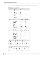
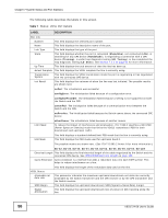
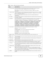
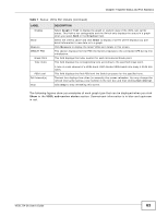
Chapter 7 System Status and Port Statistics Table 7 Status: VDSL Port Details (continued) LABEL DESCRIPTION Interleaving Depth Interleaving Block Actual Latency Path Ptm Status This field displays the actual interleaving depth. The value ranges from 1 to 4096 with an increment of 1. The value 1 indicates no interleaving. This field displays the actual interleaving block length. The value ranges from 4 to 255 with an increment of 1. This field displays the ID of the channel the Switch is using for that port. All the following fields describe the status for this channel. Packet Transfer Mode is a packet-based (for example, for Ethernet packets, IP packets, etc.) transmission method applied in VDSL2. It can highly increase the efficiency of packet transmission. This field displays the current state of the VDSL channel in packet transfer mode. noDefect: means both Switch and CPE device did not detect any failure or the channel is not using packet transfer mode. outOfSync: means an out of synchronization failure was detected. Actual RA Mode This field displays actual rate adaptive mode. n/a: no CPE device is connected to this port. RA mode at init: the Switch keeps the transmission rate negotiated between the Switch and CPE devices. It ranges from the configured minimum to the maximum net data rate (set in the VDSL Setup > VDSL Profile > ChanProfile screen) based on the initial line condition. The Switch automatically resumes a dropped link and adjusts the data rate back to the allowed range. Fixed rate mode: the Switch fixes the transmission rate as the minimum net data rate and disables transmission rate adjustment. If the attainable speeds cannot match configured speeds, then the VDSL link may go down or link communications may be sporadic due to line errors and consequent retransmissions. The Switch does not automatically resume a dropped link if you use this mode. Dynamic rate adaptation: the Switch dynamically changes the transmission rate negotiated between the Switch and CPE devices during initialization as well as during SHOWTIME status. This mode increases the line's stability and avoid the line being easily dropped when noise occurs. However, it may cause crosstalk noise during transmission rate adjustment. Retransmission Mode SOS enabled: the Switch uses the emergency rate adjustment system for immediate rate adjustment to avoid crosstalk noise. See SOS on page 100 for more information. This field displays G.INP retransmission mode. n/a: no CPE device is connected to this port. RTX in use: G.INP retransmission is enabled on the Switch. Mode Forbidden: G.INP retransmission is disabled on the Switch. G.INP Framing Type CPE not support: The connected CPE device does not support G.INP retransmission. This field displays the DTU (Data Transfer Unit) framing type used when G.INP is enabled. 0: G.INP is disabled on the Switch. 1: The DTU doesn't contain an 8-bit CRC. 2: There is an additional 8-bit CRC inserted at the end of the DTU. 3: An 8-bit CRC is inserted as the first octet of the DTU. 4: An 8-bit CRC is inserted as the first byte of the DTU. 60 VES1724-56 User's Guide
-
 1
1 -
2
-
3
-
4
-
5
-
6
-
7
-
8
-
9
-
10
-
11
-
12
-
13
-
14
-
15
-
16
-
17
-
18
-
19
-
20
-
21
-
22
-
23
-
24
-
25
-
26
-
27
-
28
-
29
-
30
-
31
-
32
-
33
-
34
-
35
-
36
-
37
-
38
-
39
-
40
-
41
-
42
-
43
-
44
-
45
-
46
-
47
-
48
-
49
-
50
-
51
-
52
-
53
-
54
-
 55
55 -
 56
56 -
 57
57 -
 58
58 -
 59
59 -
 60
60 -
 61
61 -
 62
62 -
 63
63 -
 64
64 -
 65
65 -
66
-
67
-
68
-
69
-
70
-
71
-
72
-
73
-
74
-
75
-
76
-
77
-
78
-
79
-
80
-
81
-
82
-
83
-
84
-
85
-
86
-
87
-
88
-
89
-
90
-
91
-
92
-
93
-
94
-
95
-
96
-
97
-
98
-
99
-
100
-
101
-
102
-
103
-
104
-
105
-
106
-
107
-
108
-
109
-
110
-
111
-
112
-
113
-
114
-
115
-
116
-
117
-
118
-
119
-
120
-
121
-
122
-
123
-
124
-
125
-
126
-
127
-
128
-
129
-
130
-
131
-
132
-
133
-
134
-
135
-
136
-
137
-
138
-
139
-
140
-
141
-
142
-
143
-
144
-
145
-
146
-
147
-
148
-
149
-
150
-
151
-
152
-
153
-
154
-
155
-
156
-
157
-
158
-
159
-
160
-
161
-
162
-
163
-
164
-
165
-
166
-
167
-
168
-
169
-
170
-
171
-
172
-
173
-
174
-
175
-
176
-
177
-
178
-
179
-
180
-
181
-
182
-
183
-
184
-
185
-
186
-
187
-
188
-
189
-
190
-
191
-
192
-
193
-
194
-
195
-
196
-
197
-
198
-
199
-
200
-
201
-
202
-
203
-
204
-
205
-
206
-
207
-
208
-
209
-
210
-
211
-
212
-
213
-
214
-
215
-
216
-
217
-
218
-
219
-
220
-
221
-
222
-
223
-
224
-
225
-
226
-
227
-
228
-
229
-
230
-
231
-
232
-
233
-
234
-
235
-
236
-
237
-
238
-
239
-
240
-
241
-
242
-
243
-
244
-
245
-
246
-
247
-
248
-
249
-
250
-
251
-
252
-
253
-
254
-
255
-
256
-
257
-
258
-
259
-
260
-
261
-
262
-
263
-
264
-
265
-
266
-
267
-
268
-
269
-
270
-
271
-
272
-
273
-
274
-
275
-
276
-
277
-
278
-
279
-
280
-
281
-
282
-
283
-
284
-
285
-
286
-
287
-
288
-
289
-
290
-
291
-
292
-
293
-
294
-
295
-
296
-
297
-
298
-
299
-
300
-
301
-
302
-
303
-
304
-
305
-
306
-
307
-
308
-
309
-
310
-
311
-
312
-
313
-
314
-
315
-
316
-
317
-
318
-
319
-
320
-
321
-
322
-
323
-
324
-
325
-
326
-
327
-
328
-
329
-
330
-
331
-
332
-
333
-
334
-
335
-
336
-
337
-
338
-
339
-
340
-
341
-
342
-
343
-
344
-
345
-
346
-
347
-
348
-
349
-
350
-
351
-
352
-
353
-
354
-
355
-
356
-
357
-
358
-
359
-
360
-
361
-
362
-
363
-
364
-
365
-
366
-
367
-
368
-
369
-
370
-
371
-
372
-
373
-
374
-
375
-
376
-
377
-
378
-
379
-
380
-
381
-
382
-
383
-
384
-
385
-
386
-
387
-
388
-
389
-
390
-
391
-
392
-
393
-
394
-
395
-
396
-
397
-
398
-
399
-
400
-
401
-
402
-
403
-
404
-
405
-
406
-
407
-
408
-
409
-
410
-
411
-
412
-
413
-
414
 |
 |
