ZyXEL VES1724-56B2 User Guide - Page 121
VDSL Alarm Template Setup
 |
View all ZyXEL VES1724-56B2 manuals
Add to My Manuals
Save this manual to your list of manuals |
Page 121 highlights
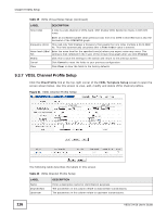
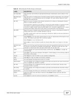
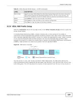
Chapter 9 VDSL Setup Table 42 Impulse Noise Monitor Setup (continued) LABEL IAT Offset IAT Step ISDD Sensitivity Add Cancel Clear Name InpEqMode INMCC IATO IATS Applied Ports Delete Cancel DESCRIPTION Specify the IAT offset from 3 to 511 DMT symbols. This is to determine in which bin (category) of the IAT histogram the IAT is reported. There are eight bins (0 to 7) in an IAT histogram. An IAT is logged in bin y (where y can be from 1 to 6) if the reported IAT value is in the range from (IAT Offset + (y -1) x (2IATStep)) to ((IAT Offset - 1) + (y) x (2IATStep)). If an impulse event occurs at an interval less than the specified IAT offset, the IAT will be logged in bin 0 of the IAT histogram. Any IAT greater than or equal to (IAT Offset + 6 x 2IATStep) will be recorded in bin 7. Specify the IAT step from 0 to 7. This is to determine in which bin (category) of the IAT histogram the IAT is reported. Specify the Impulse noise threshold of Severely Degraded symbol Detection from -12.8dB to +12.7 dB in steps of 0.1 dB. The smaller the value, the more sensitive the signal against impulse noise. For example, -12.8 dB is more sensitive to the symbol affected by impulse noise than +12.7 dB. Click Add to save the new settings to the Switch. It then displays in the summary table at the bottom of the screen. Click Cancel to reset the fields to your previous configuration. Click Clear to clear the fields to the factory defaults. This field displays the descriptive name of a profile. This field displays the configured upstream and downstream INPEq modes in a profile. This field displays the configured upstream and downstream INMCC values in a profile. This field displays the configured upstream and downstream IAT offsets in a profile. This field displays the configured upstream and downstream IAT steps in a profile. This field displays the VDSL port number(s) to which this profile is applied. Check the rule(s) that you want to remove in the Delete column and then click the Delete button. Click Cancel to clear the selected checkboxes in the Delete column. 9.4 VDSL Alarm Template Setup Alarm profiles define VDSL port alarm thresholds. The device sends an alarm trap and generates a syslog entry when the thresholds of the alarm profile are exceeded. VES1724-56 User's Guide 121
-
 1
1 -
2
-
3
-
4
-
5
-
6
-
7
-
8
-
9
-
10
-
11
-
12
-
13
-
14
-
15
-
16
-
17
-
18
-
19
-
20
-
21
-
22
-
23
-
24
-
25
-
26
-
27
-
28
-
29
-
30
-
31
-
32
-
33
-
34
-
35
-
36
-
37
-
38
-
39
-
40
-
41
-
42
-
43
-
44
-
45
-
46
-
47
-
48
-
49
-
50
-
51
-
52
-
53
-
54
-
55
-
56
-
57
-
58
-
59
-
60
-
61
-
62
-
63
-
64
-
65
-
66
-
67
-
68
-
69
-
70
-
71
-
72
-
73
-
74
-
75
-
76
-
77
-
78
-
79
-
80
-
81
-
82
-
83
-
84
-
85
-
86
-
87
-
88
-
89
-
90
-
91
-
92
-
93
-
94
-
95
-
96
-
97
-
98
-
99
-
100
-
101
-
102
-
103
-
104
-
105
-
106
-
107
-
108
-
109
-
110
-
111
-
112
-
113
-
114
-
115
-
 116
116 -
 117
117 -
 118
118 -
 119
119 -
 120
120 -
 121
121 -
 122
122 -
 123
123 -
 124
124 -
 125
125 -
 126
126 -
127
-
128
-
129
-
130
-
131
-
132
-
133
-
134
-
135
-
136
-
137
-
138
-
139
-
140
-
141
-
142
-
143
-
144
-
145
-
146
-
147
-
148
-
149
-
150
-
151
-
152
-
153
-
154
-
155
-
156
-
157
-
158
-
159
-
160
-
161
-
162
-
163
-
164
-
165
-
166
-
167
-
168
-
169
-
170
-
171
-
172
-
173
-
174
-
175
-
176
-
177
-
178
-
179
-
180
-
181
-
182
-
183
-
184
-
185
-
186
-
187
-
188
-
189
-
190
-
191
-
192
-
193
-
194
-
195
-
196
-
197
-
198
-
199
-
200
-
201
-
202
-
203
-
204
-
205
-
206
-
207
-
208
-
209
-
210
-
211
-
212
-
213
-
214
-
215
-
216
-
217
-
218
-
219
-
220
-
221
-
222
-
223
-
224
-
225
-
226
-
227
-
228
-
229
-
230
-
231
-
232
-
233
-
234
-
235
-
236
-
237
-
238
-
239
-
240
-
241
-
242
-
243
-
244
-
245
-
246
-
247
-
248
-
249
-
250
-
251
-
252
-
253
-
254
-
255
-
256
-
257
-
258
-
259
-
260
-
261
-
262
-
263
-
264
-
265
-
266
-
267
-
268
-
269
-
270
-
271
-
272
-
273
-
274
-
275
-
276
-
277
-
278
-
279
-
280
-
281
-
282
-
283
-
284
-
285
-
286
-
287
-
288
-
289
-
290
-
291
-
292
-
293
-
294
-
295
-
296
-
297
-
298
-
299
-
300
-
301
-
302
-
303
-
304
-
305
-
306
-
307
-
308
-
309
-
310
-
311
-
312
-
313
-
314
-
315
-
316
-
317
-
318
-
319
-
320
-
321
-
322
-
323
-
324
-
325
-
326
-
327
-
328
-
329
-
330
-
331
-
332
-
333
-
334
-
335
-
336
-
337
-
338
-
339
-
340
-
341
-
342
-
343
-
344
-
345
-
346
-
347
-
348
-
349
-
350
-
351
-
352
-
353
-
354
-
355
-
356
-
357
-
358
-
359
-
360
-
361
-
362
-
363
-
364
-
365
-
366
-
367
-
368
-
369
-
370
-
371
-
372
-
373
-
374
-
375
-
376
-
377
-
378
-
379
-
380
-
381
-
382
-
383
-
384
-
385
-
386
-
387
-
388
-
389
-
390
-
391
-
392
-
393
-
394
-
395
-
396
-
397
-
398
-
399
-
400
-
401
-
402
-
403
-
404
-
405
-
406
-
407
-
408
-
409
-
410
-
411
-
412
-
413
-
414
 |
 |
