3Com 3CRWE875075ATAA User Guide - Page 19
Hecking, Ounting
 |
UPC - 662705487465
View all 3Com 3CRWE875075ATAA manuals
Add to My Manuals
Save this manual to your list of manuals |
Page 19 highlights
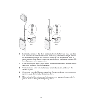
4 To link the access point to your Ethernet network, plug one end of another Ethernet cable into the port labeled To Hub/Switch on the power supply, and plug the other end into a LAN port (on a hub or in a wall). USING A POWER-OVER-ETHERNET LAN PORT If your LAN equipment complies with the IEEE 802.3af power-over-Ethernet standard, you can connect the access point directly to a LAN port. For example, the illustration above right shows a connection through a 3Com Ethernet Power Supply to a 3Com SuperStack® Switch. CHECKING THE LEDS When power is connected, the access point LEDs light. The illustration and the following table describe the LEDs and their functions. Name Description Radio LED blinks red to indicate radio activity. Faster blinking indicates more activity. Power Reset Button Reset Button LED lights green when operational code is running. Press this button and hold for 15 seconds to restore the factory defaults. Ethernet LED lights yellow when Ethernet link is established. LED blinks to indicate activity on the Ethernet. Faster blinking indicates more activity. Radio LED blinks red to indicate radio activity. Faster blinking indicates more activity. (This LED is only active when a second radio is installed.) MOUNTING ON A WALL CAUTION: The mounting plate is designed for wall mount installation only. To avoid equipment damage and possible injury, do not use the mounting plate for a ceiling installation. The access point comes equipped with all the necessary hardware for mounting on a wall, including a mounting plate. For a secure installation, the mounting plate should be placed perpendicular to the floor, with the arrow pointed up, as indicated on the mounting plate, with the smooth side against the wall. 19
-
 1
1 -
2
-
3
-
4
-
5
-
6
-
7
-
8
-
9
-
10
-
11
-
12
-
13
-
 14
14 -
 15
15 -
 16
16 -
 17
17 -
 18
18 -
 19
19 -
 20
20 -
 21
21 -
 22
22 -
 23
23 -
 24
24 -
25
-
26
-
27
-
28
-
29
-
30
-
31
-
32
-
33
-
34
-
35
-
36
-
37
-
38
-
39
-
40
-
41
-
42
-
43
-
44
-
45
-
46
-
47
-
48
-
49
-
50
-
51
-
52
-
53
-
54
-
55
-
56
-
57
-
58
-
59
-
60
-
61
-
62
-
63
-
64
 |
 |
