3Com 3CRWE875075ATAA User Guide - Page 20
opening for a seamless appearance using one of the methods illustrated below.
 |
UPC - 662705487465
View all 3Com 3CRWE875075ATAA manuals
Add to My Manuals
Save this manual to your list of manuals |
Page 20 highlights
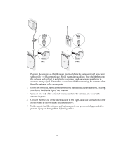
1 Install the mounting plate as shown in the following illustration, on either a stud (or other hard wall surface), or onto drywall. If installing into a stud or other secure vertical surface, use 2 screws. If installing into drywall, use 3 plastic anchors and 3 screws. o Allow for a clearance of at least 25 cm (10 Inches) between the ceiling and the top of the mounting plate. o Make sure that "UP" or "A" is oriented toward the top of the bracket, and align the mounting plate screw holes vertically. o For installation on a wall stud, install the top screw into the stud, as shown at left in the illustration, and then vertically align the mounting plate before installing the bottom screw. o For installation on to drywall, mark three screw holes using the mounting plate as a template for vertical alignment, as shown at right in the illustration above. o Use a 5-mm (3/16-in.) drill bit if using the plastic anchors provided. o For drywall mounts, you can route the cable through either a side or center opening for a seamless appearance using one of the methods illustrated below. Alternatively, you can simply attach the Ethernet cable to the side of the unit, allowing it to trail along the wall. o If you have routed the Ethernet cable through the center opening, secure the cable on the hook located on the mounting plate as shown in the illustration below. 2 Connect the Ethernet cable to the Ethernet port on the access point. 20
-
 1
1 -
2
-
3
-
4
-
5
-
6
-
7
-
8
-
9
-
10
-
11
-
12
-
13
-
14
-
 15
15 -
 16
16 -
 17
17 -
 18
18 -
 19
19 -
 20
20 -
 21
21 -
 22
22 -
 23
23 -
 24
24 -
 25
25 -
26
-
27
-
28
-
29
-
30
-
31
-
32
-
33
-
34
-
35
-
36
-
37
-
38
-
39
-
40
-
41
-
42
-
43
-
44
-
45
-
46
-
47
-
48
-
49
-
50
-
51
-
52
-
53
-
54
-
55
-
56
-
57
-
58
-
59
-
60
-
61
-
62
-
63
-
64
 |
 |
