3Ware 9500S-4LP Installation Guide - Page 108
Tools and equipment required, Installation Overview, Battery Backup Unit BBU and battery
 |
UPC - 693494950045
View all 3Ware 9500S-4LP manuals
Add to My Manuals
Save this manual to your list of manuals |
Page 108 highlights
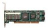
Appendix A. Installing the Battery Backup Unit Tools and equipment required „ Phillips-head screwdriver „ Grounding strap „ Battery Backup Unit (BBU) and battery „ 3ware 9000 series controller Installation Overview The Battery Backup Unit (BBU) attaches to the controller at three points, as illustrated in Figures 1 through 3: a Slots on the edge of the controller (visible after removing the PCI bracket) match to clips on the BBU b Receptacle on the controller matches to connector on the BBU c Post hole on the controller mates to post on the BBU a) Clips b) BBU connector c) post Figure 1. Points of connection on the BBU (bottom view) 100 3ware 9000 Series Serial ATA RAID Controller Installation Guide
-
 1
1 -
2
-
3
-
4
-
5
-
6
-
7
-
8
-
9
-
10
-
11
-
12
-
13
-
14
-
15
-
16
-
17
-
18
-
19
-
20
-
21
-
22
-
23
-
24
-
25
-
26
-
27
-
28
-
29
-
30
-
31
-
32
-
33
-
34
-
35
-
36
-
37
-
38
-
39
-
40
-
41
-
42
-
43
-
44
-
45
-
46
-
47
-
48
-
49
-
50
-
51
-
52
-
53
-
54
-
55
-
56
-
57
-
58
-
59
-
60
-
61
-
62
-
63
-
64
-
65
-
66
-
67
-
68
-
69
-
70
-
71
-
72
-
73
-
74
-
75
-
76
-
77
-
78
-
79
-
80
-
81
-
82
-
83
-
84
-
85
-
86
-
87
-
88
-
89
-
90
-
91
-
92
-
93
-
94
-
95
-
96
-
97
-
98
-
99
-
100
-
101
-
102
-
 103
103 -
 104
104 -
 105
105 -
 106
106 -
 107
107 -
 108
108 -
 109
109 -
 110
110 -
 111
111 -
 112
112 -
 113
113 -
114
-
115
-
116
-
117
-
118
-
119
-
120
-
121
-
122
-
123
-
124
-
125
-
126
 |
 |

Appendix A. Installing the Battery Backup Unit
100
3ware 9000 Series Serial ATA RAID Controller Installation Guide
Tools and equipment required
Phillips-head screwdriver
Grounding strap
Battery Backup Unit (BBU) and battery
3ware 9000 series controller
Installation Overview
The Battery Backup Unit (BBU) attaches to the controller at three
points, as illustrated in Figures 1 through 3:
a
Slots on the edge of the controller (visible after removing the
PCI bracket) match to clips on the BBU
b
Receptacle on the controller matches to connector on the BBU
c
Post hole on the controller mates to post on the BBU
Figure 1. Points of connection on the BBU (bottom view)
c) post
a) Clips
b) BBU connector