Asus CM1745 CM1745 User's Manual - Page 14
Audio 2
 |
View all Asus CM1745 manuals
Add to My Manuals
Save this manual to your list of manuals |
Page 14 highlights
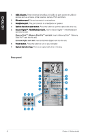
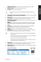
ENGLISH 13. ��R��e�a�r�S��p�e�a�k�e�r��O�u�t��p�o�r�t (�b��la�c�k�)�.� This port connects to the rear speakers in a 4, 6, and 8-channel audio configuration. 14. ��S��id�e��S�p��e�a�k�e�r��O�u�t��p�o�r�t (�g��ra�y�)�.� This port connects to the side speakers in an 8-channel audio configuration. 15. ��M��ic�r�o�p��h�o�n�e��p�o�r�t �(�p�in�k��)�. This port connects to a microphone. 16. ��L��in��e�O��u�t�p��o�r�t �(�li�m�e��)�. This port connects to a headphone or speaker. In a 4, 6, or 8-channel configuration, the function of this port becomes Front Speaker Out. 17. ��C��e�n�t�e�r/�S�u�b��w�o�o��fe�r��p�o�r�t �(�o�ra�n�g��e�)�. This port connects to the center/subwoofer speakers. 18. ���L�in��e��In��p��o�r�t �(�li�g�h��t�b�l�u�e��)�. This port connects to a tape, CD, DVD player, or other audio sources. Refer to the audio configuration table below for the function of the audio ports in a 2, 4, 6, or 8-channel configuration. Audio 2, 4, 6, or 8-channel configuration Port Light Blue Lime Pink Orange Black Gray Headset 2-channel Line In Line Out Mic In - - - 4-channel Line In Front Speaker Out Mic In - Rear Speaker Out - 6-channel Line In Front Speaker Out Mic In Center/Subwoofer Rear Speaker Out - 8-channel Line In Front Speaker Out Mic In Center/Subwoofer Rear Speaker Out Side Speaker Out 19. ��A�S��U�S��G�r�a�p�h�i�c�s�C��a�rd� (�o��n�s��e�le�c�t�e�d��m��o�d�e�l�s�o��n�ly��)�. The display output ports on this optional ASUS Graphics Card may vary with different models. 20. ASUS WLAN Card (on selected models only). This optional WLAN card allows your computer to connect to a wireless network. 21. ��E��x�p�a�n�s�i�o�n��s�lo��t�b�r�a�c�k�e�t�. Remove the expansion slot bracket when installing an expansion card. 14 Chapter 1: Getting started
-
 1
1 -
2
-
3
-
4
-
5
-
6
-
7
-
8
-
 9
9 -
 10
10 -
 11
11 -
 12
12 -
 13
13 -
 14
14 -
 15
15 -
 16
16 -
 17
17 -
 18
18 -
 19
19 -
20
-
21
-
22
-
23
-
24
-
25
-
26
-
27
-
28
-
29
-
30
-
31
-
32
-
33
-
34
-
35
-
36
-
37
-
38
-
39
-
40
-
41
-
42
-
43
-
44
-
45
-
46
-
47
-
48
-
49
-
50
-
51
-
52
-
53
-
54
-
55
-
56
-
57
-
58
-
59
-
60
-
61
-
62
-
63
-
64
-
65
-
66
 |
 |