Asus P4GE-MX P4GE-MX User Manual E1722 English Edition - Page 26
Internal connectors
 |
View all Asus P4GE-MX manuals
Add to My Manuals
Save this manual to your list of manuals |
Page 26 highlights
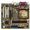
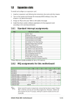
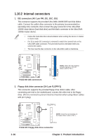
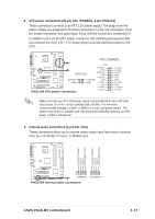
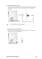
1.10.2 Internal connectors 1. IDE connectors (40-1 pin PRI_IDE, SEC_IDE) This connector supports the provided Ultra DMA 100/66 IDE hard disk ribbon cable. Connect the cable's blue connector to the primary (recommended) or secondary IDE connector, then connect the gray connector to the Ultra DMA 100/66 slave device (hard disk drive) and the black connector to the Ultra DMA 100/66 master device. • Follow the hard disk drive documentation when setting the device in master or slave mode. • Pin 20 on each IDE connector is removed to match the covered hole on the Ultra DMA cable connector. This prevents incorrect orientation when you connect the cables. • The hole near the blue connector on the Ultra DMA cable is intentional. SEC_IDE PRI_IDE ® P4GE-MX NOTE: Orient the red markings (usually zigzag) on the IDE ribbon cable to PIN 1. P4GE-MX IDE connectors PIN 1 2. Floppy disk drive connector (34-1 pin FLOPPY1) This connector supports the provided floppy drive ribbon cable. After connecting one end to the motherboard, connect the other end to the floppy drive. (Pin 5 is removed to prevent incorrect insertion when using ribbon cables with pin 5 plug). FLOPPY1 ® P4GE-MX NOTE: Orient the red markings on the floppy ribbon cable to PIN 1. PIN 1 P4GE-MX Floppy disk drive connector 1-16 Chapter 1: Product introduction
-
 1
1 -
2
-
3
-
4
-
5
-
6
-
7
-
8
-
9
-
10
-
11
-
12
-
13
-
14
-
15
-
16
-
17
-
18
-
19
-
20
-
 21
21 -
 22
22 -
 23
23 -
 24
24 -
 25
25 -
 26
26 -
 27
27 -
 28
28 -
 29
29 -
 30
30 -
 31
31 -
32
-
33
-
34
-
35
-
36
-
37
-
38
-
39
-
40
-
41
-
42
-
43
-
44
-
45
-
46
-
47
-
48
-
49
-
50
-
51
-
52
-
53
-
54
-
55
-
56
-
57
-
58
-
59
-
60
-
61
-
62
 |
 |