Asus P4GE-MX P4GE-MX User Manual E1722 English Edition - Page 29
Chassis intrusion connector 4-1 pin CHASSIS1, Front panel audio connector 10-1 pin FP_AUDIO
 |
View all Asus P4GE-MX manuals
Add to My Manuals
Save this manual to your list of manuals |
Page 29 highlights
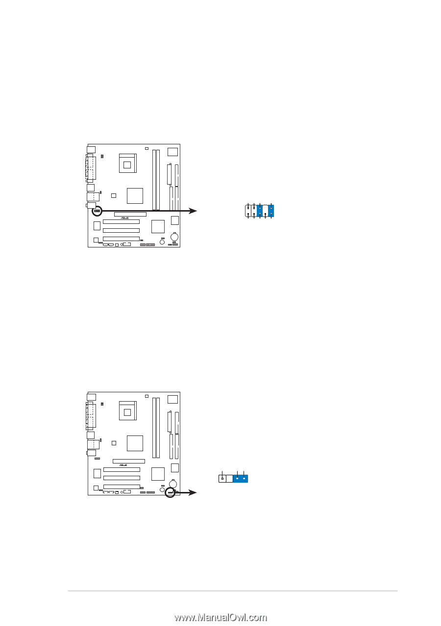
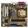
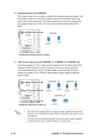
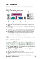
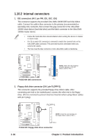
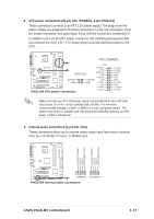
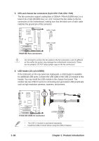
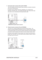
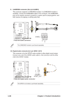
7. Front panel audio connector (10-1 pin FP_AUDIO) This is an interface for the front panel cable that allows convenient connection and control of audio devices. Be default, the pins labeled LINE OUT_R/BLINE_OUT_R and the pins LINE OUT_L/BLINE_OUT_L are shorted with jumper caps. Remove the caps only when you are connecting the front panel audio cable. AGND +5VA BLINE_OUT_R BLINE_OUT_L ® P4GE-MX FP_AUDIO MIC2 MICPWR Line out_R NC Line out_L P4GE-MX Front panel audio connector 8. Chassis intrusion connector (4-1 pin CHASSIS1) This lead is for a chassis designed with intrusion detection feature. This requires an external detection mechanism such as a chassis intrusion sensor or microswitch. When you remove any chassis component, the sensor triggers and sends a high-level signal to this lead to record a chassis intrusion event. By default, the pins labeled "Chassis Signal" and "Ground" are shorted with a jumper cap. If you wish to use the chassis intrusion detection feature, remove the jumper cap from the pins. CHASSIS +5VSB_MB Chassis Signal GND ® P4GE-MX (Default) P4GE-MX Chassis intrusion connector ASUS P4GE-MX motherboard 1-19
-
 1
1 -
2
-
3
-
4
-
5
-
6
-
7
-
8
-
9
-
10
-
11
-
12
-
13
-
14
-
15
-
16
-
17
-
18
-
19
-
20
-
21
-
22
-
23
-
 24
24 -
 25
25 -
 26
26 -
 27
27 -
 28
28 -
 29
29 -
 30
30 -
 31
31 -
 32
32 -
 33
33 -
 34
34 -
35
-
36
-
37
-
38
-
39
-
40
-
41
-
42
-
43
-
44
-
45
-
46
-
47
-
48
-
49
-
50
-
51
-
52
-
53
-
54
-
55
-
56
-
57
-
58
-
59
-
60
-
61
-
62
 |
 |