Asus P4GE-MX P4GE-MX User Manual E1722 English Edition - Page 31
Serial connector 9-pin COM2, Power LED connector 3-pin PLED1
 |
View all Asus P4GE-MX manuals
Add to My Manuals
Save this manual to your list of manuals |
Page 31 highlights
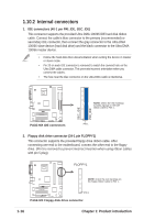
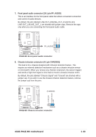
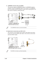
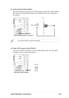
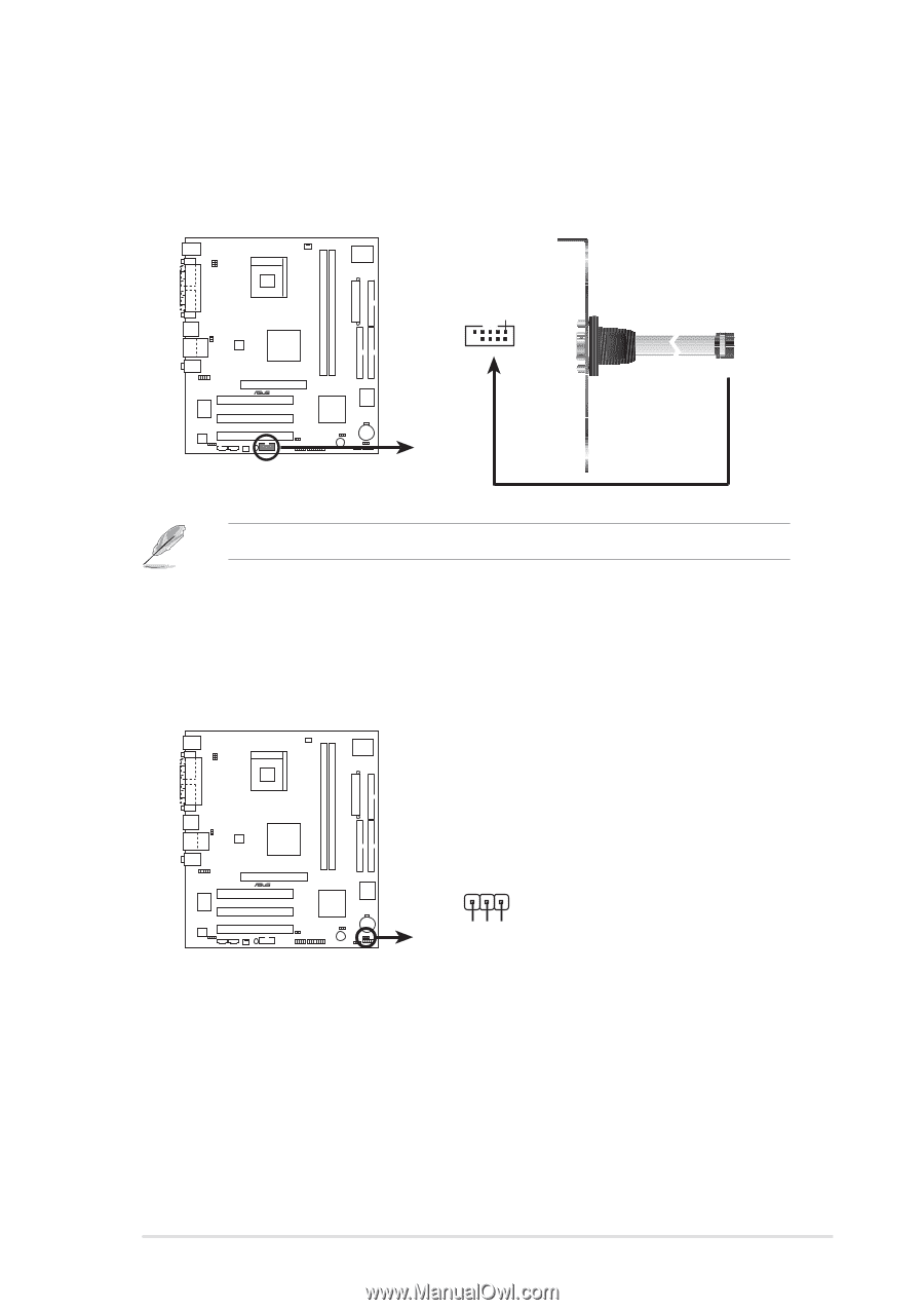
11. Serial connector (9-pin COM2 ) This 9-pin connector connects to a COM2 bracket. Connect the COM2 cable to this connector and install the bracket on an available slot in the rear panel of the chassis. ® P4GE-MX PIN 1 COM2 P4GE-MX Serial port connector The COM2 bracket is purchased separately. 12. Power LED connector (3-pin PLED1 ) This 3-pin connector connects to a 3-pin system power LED. The LED lights up when you turn on the system power. ® P4GE-MX P4GE-MX PLED setting PLED+ NC PLED- PLED1 1 ASUS P4GE-MX motherboard 1-21
-
 1
1 -
2
-
3
-
4
-
5
-
6
-
7
-
8
-
9
-
10
-
11
-
12
-
13
-
14
-
15
-
16
-
17
-
18
-
19
-
20
-
21
-
22
-
23
-
24
-
25
-
 26
26 -
 27
27 -
 28
28 -
 29
29 -
 30
30 -
 31
31 -
 32
32 -
 33
33 -
 34
34 -
 35
35 -
 36
36 -
37
-
38
-
39
-
40
-
41
-
42
-
43
-
44
-
45
-
46
-
47
-
48
-
49
-
50
-
51
-
52
-
53
-
54
-
55
-
56
-
57
-
58
-
59
-
60
-
61
-
62
 |
 |
ASUS P4GE-MX motherboard
1-21
11.
Serial connector (9-pin COM2 )
This 9-pin connector connects to a COM2 bracket. Connect the COM2 cable to
this connector and install the bracket on an available slot in the rear panel of
the chassis.
The COM2 bracket is purchased separately.
P4GE-MX Serial port connector
PIN 1
COM2
P4GE-MX
12. Power LED connector (3-pin PLED1 )
This 3-pin connector connects to a 3-pin system power LED.
The LED lights
up when you turn on the system power.
P4GE-MX
P4GE-MX PLED setting
PLED1
PLED+
1
NC
PLED-