Asus P5LD-MR User Manual - Page 33
System memory
 |
View all Asus P5LD-MR manuals
Add to My Manuals
Save this manual to your list of manuals |
Page 33 highlights
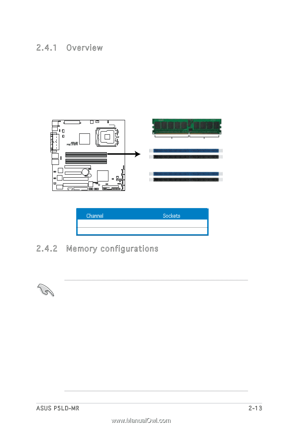
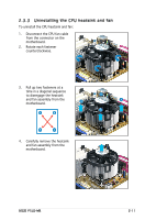
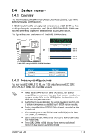
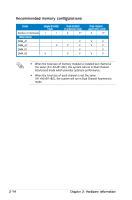
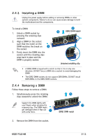
2.4 System memory 2.4.1 Overview The motherboard comes with four Double Data Rate 2 (DDR2) Dual Inline Memory Modules (DIMM) sockets. A DDR2 module has the same physical dimensions as a DDR DIMM but has a 240-pin footprint compared to the 184-pin DDR DIMM. DDR2 DIMMs are notched differently to prevent installation on a DDR DIMM socket. The figure illustrates the location of the DDR2 DIMM sockets: R P5LD-MR 128 Pins 112 Pins DIMM_A1 DIMM_A2 P5LD-MR 240-pin DDR2 DIMM Sockets DIMM_B1 DIMM_B2 Channel Channel A Channel B Sockets DIMM_A1 and DIMM_A2 DIMM_B1 and DIMM_B2 2.4.2 Memory configurations You may install 256 MB, 512 MB, and 1 GB unbuffered non‑ECC DDR2 400/533/667 DIMMs into the DIMM sockets. • Always install DIMMs with the same CAS latency. For optimum compatibility, we recommend that you obtain memory modules from the same vendor. Refer to the DDR2 Qualified Vendors List on the ASUS web site (www.asus.com). • Due to chipset resource allocation, the system may detect less than 4 GB of system memory when you installed four 1 GB DDR memory modules. • Due to chipset limitation, DDR2 667 4-4-4 is not supported on this motherboard. • When installing one or two DIMMs, install the DIMM(s) to the black slots (DIMM_A2/DIMM_B2). • Due to shared chipset memory, the total size of momories installed may reduce 8MB. • Three DDR2 DIMMs intalled into any three memory sockets will function in dual-channel asymmetric mode. ASUS P5LD-MR 2-13
-
 1
1 -
2
-
3
-
4
-
5
-
6
-
7
-
8
-
9
-
10
-
11
-
12
-
13
-
14
-
15
-
16
-
17
-
18
-
19
-
20
-
21
-
22
-
23
-
24
-
25
-
26
-
27
-
 28
28 -
 29
29 -
 30
30 -
 31
31 -
 32
32 -
 33
33 -
 34
34 -
 35
35 -
 36
36 -
 37
37 -
 38
38 -
39
-
40
-
41
-
42
-
43
-
44
-
45
-
46
-
47
-
48
-
49
-
50
-
51
-
52
-
53
-
54
-
55
-
56
-
57
-
58
-
59
-
60
-
61
-
62
-
63
-
64
-
65
-
66
-
67
-
68
-
69
-
70
-
71
-
72
-
73
-
74
-
75
-
76
-
77
-
78
-
79
-
80
-
81
-
82
-
83
-
84
-
85
-
86
-
87
-
88
-
89
-
90
-
91
-
92
-
93
-
94
-
95
-
96
-
97
-
98
-
99
-
100
-
101
-
102
-
103
-
104
-
105
-
106
-
107
-
108
-
109
-
110
-
111
-
112
-
113
-
114
-
115
-
116
-
117
-
118
-
119
-
120
-
121
-
122
-
123
-
124
-
125
-
126
-
127
-
128
-
129
-
130
-
131
-
132
-
133
-
134
-
135
-
136
-
137
-
138
-
139
-
140
-
141
-
142
-
143
-
144
-
145
-
146
-
147
-
148
-
149
-
150
-
151
-
152
-
153
-
154
-
155
-
156
-
157
-
158
-
159
-
160
 |
 |