Asus P5LD-MR User Manual - Page 50
Rear_fan1/2, Frnt_fan1/2
 |
View all Asus P5LD-MR manuals
Add to My Manuals
Save this manual to your list of manuals |
Page 50 highlights
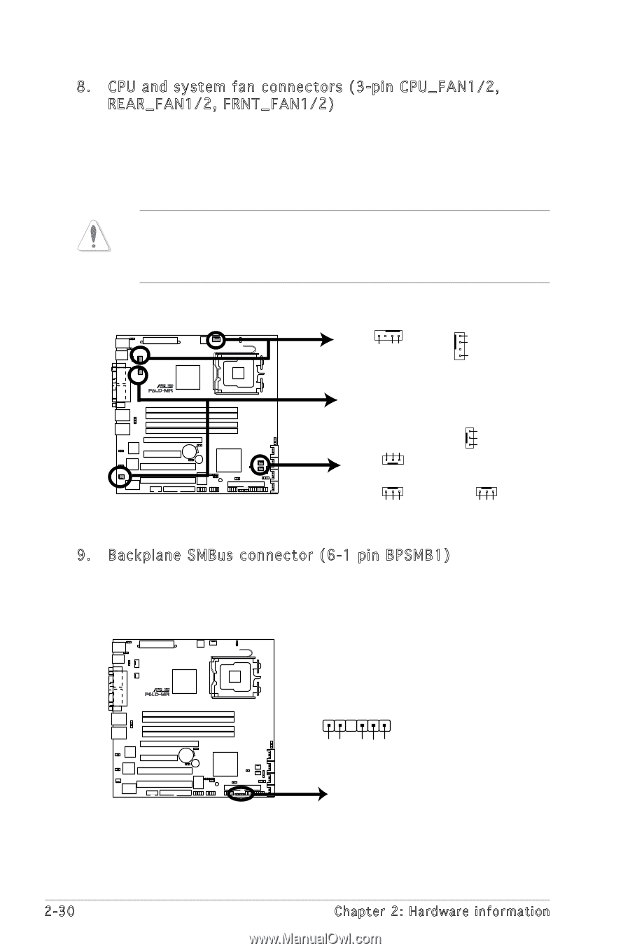
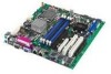
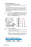
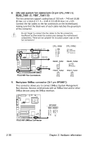
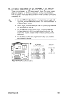
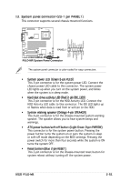
8. CPU and system fan connectors (3-pin CPU_FAN1/2, REAR_FAN1/2, FRNT_FAN1/2) The fan connectors support cooling fans of 350 mA ~ 740 mA (8.88 W max.) or a total of 2.1 A ~ 4.44 A (53.28 W max.) at +12V. Connect the fan cables to the fan connectors on the motherboard, making sure that the black wire of each cable matches the ground pin of the connector. Do not forget to connect the fan cables to the fan connectors. Insufficient air flow inside the system may damage the motherboard components. These are not jumpers! Do not place jumper caps on the fan connectors! R P5LD-MR CPU_FAN1 CPU_FAN2 REAR_FAN1 REAR_FAN2 FRNT_FAN2 FRNT_FAN1 P5LD-MR Fan Connectors CPU_FAN1 CPU_FAN2 GND FANPWR2 FANOUT4 GND FANPWR2 FANOUT4 GND +12V Rotation REAR_FAN1 REAR_FAN2 GND +12V Rotation FRNT_FAN2 FRNT_FAN1 Rotation +12V GND Rotation +12V GND 9. Backplane SMBus connector (6-1 pin BPSMB1) This connector allows you to connect SMBus (System Management Bus) devices. Devices communicate with an SMBus host and/or other SMBus devices using the SMBus interface. R P5LD-MR 1 BPSMB1 FANOUT I2C_CLK GND I2C_DATA +5V P5LD-MR SMBus Connector 2-30 Chapter 2: Hardware information
-
 1
1 -
2
-
3
-
4
-
5
-
6
-
7
-
8
-
9
-
10
-
11
-
12
-
13
-
14
-
15
-
16
-
17
-
18
-
19
-
20
-
21
-
22
-
23
-
24
-
25
-
26
-
27
-
28
-
29
-
30
-
31
-
32
-
33
-
34
-
35
-
36
-
37
-
38
-
39
-
40
-
41
-
42
-
43
-
44
-
 45
45 -
 46
46 -
 47
47 -
 48
48 -
 49
49 -
 50
50 -
 51
51 -
 52
52 -
 53
53 -
 54
54 -
 55
55 -
56
-
57
-
58
-
59
-
60
-
61
-
62
-
63
-
64
-
65
-
66
-
67
-
68
-
69
-
70
-
71
-
72
-
73
-
74
-
75
-
76
-
77
-
78
-
79
-
80
-
81
-
82
-
83
-
84
-
85
-
86
-
87
-
88
-
89
-
90
-
91
-
92
-
93
-
94
-
95
-
96
-
97
-
98
-
99
-
100
-
101
-
102
-
103
-
104
-
105
-
106
-
107
-
108
-
109
-
110
-
111
-
112
-
113
-
114
-
115
-
116
-
117
-
118
-
119
-
120
-
121
-
122
-
123
-
124
-
125
-
126
-
127
-
128
-
129
-
130
-
131
-
132
-
133
-
134
-
135
-
136
-
137
-
138
-
139
-
140
-
141
-
142
-
143
-
144
-
145
-
146
-
147
-
148
-
149
-
150
-
151
-
152
-
153
-
154
-
155
-
156
-
157
-
158
-
159
-
160
 |
 |