Asus P5LD-MR User Manual - Page 48
P5LD-MR SCSI/SATA Card Activity LED Connector
 |
View all Asus P5LD-MR manuals
Add to My Manuals
Save this manual to your list of manuals |
Page 48 highlights
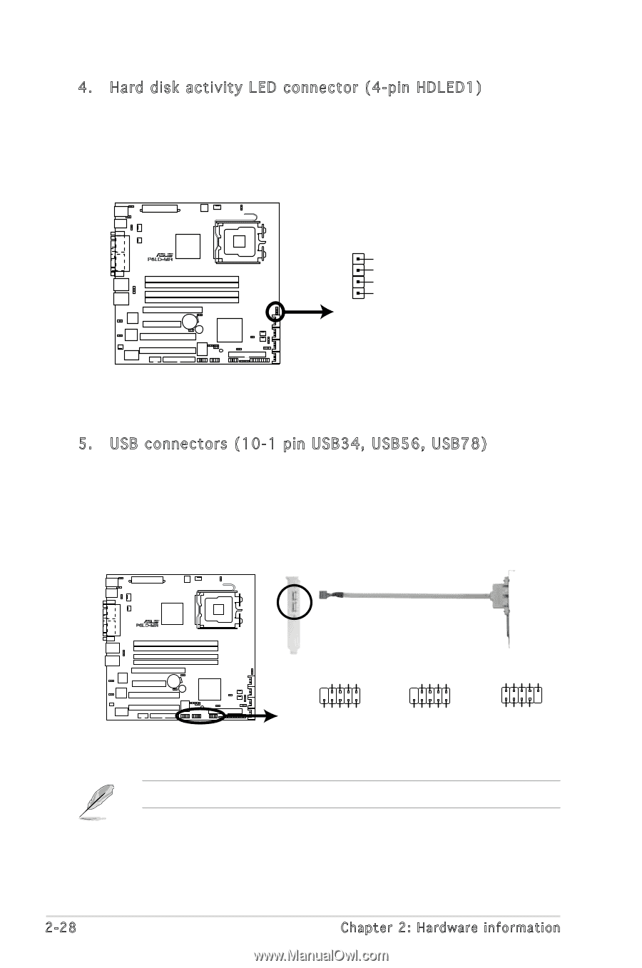
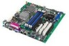
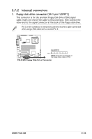
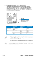
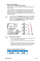
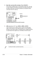
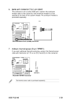
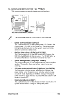
4. Hard disk activity LED connector (4-pin HDLED1) This connector supplies power to the hard disk activity LED. The read or write activities of any device connected to the SCSI connectors on the add-on SCSI card or the SATA connectors on the add-on SATA card cause this LED to light up. R P5LD-MR HDLED1 NC ADD_IN_CARD_ACT# ADD_IN_CARD_ACT# NC 1 P5LD-MR SCSI/SATA Card Activity LED Connector 5. USB connectors (10-1 pin USB34, USB56, USB78) These connectors are for USB 2.0 ports. Connect the USB module cable to this connector, then install the module to a slot opening at the back of the system chassis. This USB connector complies with USB 2.0 specification that supports up to 480 Mbps connection speed. USB+5V USB_P3USB_P3+ GND NC USB+5V USB_P2USB_P2+ GND R P5LD-MR GND USB_P2+ USB_P2USB+5V GND USB_P2+ USB_P2USB+5V NC GND USB_P3+ USB_P3USB+5V NC GND USB_P3+ USB_P3USB+5V USB34 P5LD-MR USB 2.0 Connectors USB56 USB78 The USB port module is purchased separately. 2-28 Chapter 2: Hardware information
-
 1
1 -
2
-
3
-
4
-
5
-
6
-
7
-
8
-
9
-
10
-
11
-
12
-
13
-
14
-
15
-
16
-
17
-
18
-
19
-
20
-
21
-
22
-
23
-
24
-
25
-
26
-
27
-
28
-
29
-
30
-
31
-
32
-
33
-
34
-
35
-
36
-
37
-
38
-
39
-
40
-
41
-
42
-
 43
43 -
 44
44 -
 45
45 -
 46
46 -
 47
47 -
 48
48 -
 49
49 -
 50
50 -
 51
51 -
 52
52 -
 53
53 -
54
-
55
-
56
-
57
-
58
-
59
-
60
-
61
-
62
-
63
-
64
-
65
-
66
-
67
-
68
-
69
-
70
-
71
-
72
-
73
-
74
-
75
-
76
-
77
-
78
-
79
-
80
-
81
-
82
-
83
-
84
-
85
-
86
-
87
-
88
-
89
-
90
-
91
-
92
-
93
-
94
-
95
-
96
-
97
-
98
-
99
-
100
-
101
-
102
-
103
-
104
-
105
-
106
-
107
-
108
-
109
-
110
-
111
-
112
-
113
-
114
-
115
-
116
-
117
-
118
-
119
-
120
-
121
-
122
-
123
-
124
-
125
-
126
-
127
-
128
-
129
-
130
-
131
-
132
-
133
-
134
-
135
-
136
-
137
-
138
-
139
-
140
-
141
-
142
-
143
-
144
-
145
-
146
-
147
-
148
-
149
-
150
-
151
-
152
-
153
-
154
-
155
-
156
-
157
-
158
-
159
-
160
 |
 |